Integrated Navigation & GNSS Command and Programming Manual
Rev 1.0
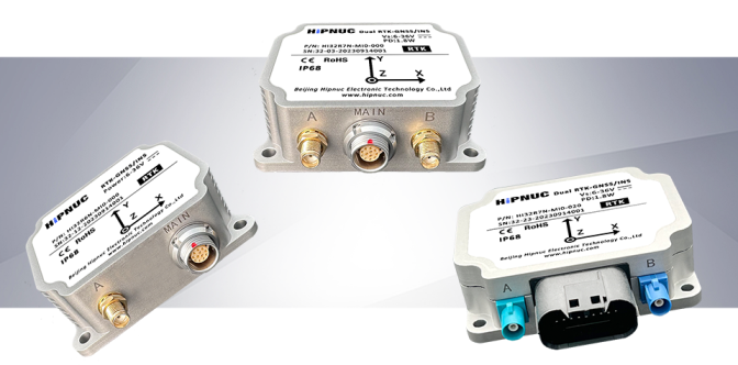
Applicable to the CH3xx / HI30 / HI32 series
Document Revision History
| Version | Date | Author | Changes |
|---|---|---|---|
| V1.0 | Oct 1, 2023 | HiPNUC | Initial version |
Module Configuration Commands
Module configuration uses ASCII string commands. Each command must end with a carriage return + line feed \r\n (similar to AT commands) before the system can recognize it.
Command Overview
| Command | Description |
|---|---|
| REBOOT | Reset |
| LOG | Request message output from the device |
| CONFIG | Configure the module |
| UNLOGALL | Cancel all message output |
| SAVECONFIG | Save configuration to Flash |
| SETBASELINE | Set the dual-antenna baseline length / tilt constraint, lever-arm compensation, etc.; takes effect after save + reboot. |
| SERIALCONFIG | Set the serial-port baud rate |
Command Reference
REBOOT
Reset and reboot, effective immediately. Equivalent to a power cycle.
LOG
ENABLE/DISABLE: turn data output on/off globally
LOG ENABLE- globally enable data-frame output (default)LOG DISABLE- globally disable data-frame output
VERSION: show module version
LOG VERSION - print firmware version information
COMCONFIG: show serial-port configuration
LOG COMCONFIG - print serial port and output-protocol configuration
INSCONFIG: show integrated-navigation configuration
LOG INSCONFIG - show the integrated-navigation configuration, including the current kinematic model, dual-antenna parameters and the NMEA Talker ID.
MOTION_MODEL=CAR
ANTA=0.0,0.0,0.0
ANTB=0.0,1.0,0.0
NMEATID=GP
OK
MSG: configure data-frame output and rate
Format: LOG <MSG> <TYPE> <PERIOD>
- MSG: GGA, RMC, SXT, HI81, etc.
- TYPE: ONTIME means periodic output
- PERIOD: output-frame period in seconds; allowed values: 1 (1 Hz), 0.5 (2 Hz), 0.1 (10 Hz), 0.02 (50 Hz), 0.01 (100 Hz), 0.005 (200 Hz)
Examples:
LOG HI81 ONTIME 0.01- set the HI81 packet output period on the current serial port to 0.01 s (100 Hz)LOG SXT ONTIME 0.05- set the SXT packet output period on the current serial port to 0.05 s (20 Hz)LOG SXT ONTIME 0- turn off SXT packet output on the current serial port
CONFIG
Configures the module's working parameters. Most commands take effect immediately, and SAVECONFIG is required to persist them across power cycles.
Configure the integrated-navigation kinematic model
CONFIG MODEL CAR(factory default) - set the model constraint to vehicle mode. In this mode the solver applies NHC (non-holonomic constraints), which significantly reduces accumulated error in GNSS-outage scenarios such as tunnels and underground garages.CONFIG MODEL SHIP- set the model constraint to marine/ship mode, reducing accumulated error during outages on ships.CONFIG MODEL PLANE- set the model constraint to aircraft mode. This mode applies no kinematic constraint and suits airborne use.CONFIG MODEL BASE- set the module to base-station mode. After this, the module locks its own position within 60 s (position no longer changes); commonly used to build a self-hosted RTK base station. The antenna must be in a good observation environment when configuring base mode.
Use LOG INSCONFIG to view the current user configuration.
Configure NTRIP differential account
This device can drive certain vendors' 4G DTU terminals or an Ethernet interface to provide network RTK: it automatically configures the DTU/Ethernet interface and feeds in RTK differential data. Steps:
- Connect COM2 to the DTU. COM2 is dedicated to the DTU and uses the 4G DTU for NTRIP RTK differential.
- The currently supported DTU model is TAS-LTE-364 (Tas 4G transparent DTU). Make sure the model is correct and that a working 4G SIM card is inserted.
- Configure the differential account:
CONFIG NTRIP <SERVER_IP> <PORT> <MNT_POINT> <USER_NAME> <PASSWD>, where:
SERVER_IP: CORS server address, a domain name or IP.PORT: CORS server portMNT_POINT: mount point, e.g.AUTOfor Qianxun, orRTCM33_GRCEfor China Mobile.USER_NAME: CORS account usernamePASSWD: CORS account password
Example - configure a Qianxun CORS account (sample username qxxrli003, password 123456):
Example: CONFIG NTRIP rtk.ntrip.qxwz.com 8002 AUTO qxxrli003 123456. This is saved across power cycles; configure it once.
- Restart the module.
- Use
LOG NTRIPCONFIGto view the current configuration. IfDTU NAMEshowsTAS-LTExxx, the module has established a link with the DTU (the module auto-negotiates the baud rate; an empty NAME means the DTU link failed). Note that a non-empty NAME only confirms the module-to-DTU link, not whether the DTU-to-network link is healthy.
DTU     NAME:  Revision: TAS-LTE-C_C4002L242_
NTRIP SERVER:  xxxxxxx.com:xxxx
NTRIP  MOUNT:  AUTO
NTRIP  UNAME:  xxxxxxx
NTRIP PASSWD: xxxxxxx- If the RTK IP/account details are correct, RTK is typically reached within ~30 s.
Save the configuration and reboot for it to take effect.
Enable the built-in SD-card data logging
Some products have an internal SD card for data logging. On each power-up a .jog file named after the power-up UTC time is created automatically. You can use an FTP tool (e.g. FileZilla) to view all files on the internal card.
CONFIG FLOG COM1 1- enable COM1 logging; all data output on the main serial port COM1 is also copied to a log file on the SD card.CONFIG FLOG COM1 0- disable COM1 logging.
UNLOGALL
Set the output rate of all periodic messages to 0 (no output).
SAVECONFIG
Save all configuration to Flash. Usually used together with REBOOT, i.e. save everything then reboot to apply.
SETBASELINE
Sets antenna A's position relative to the IMU (lever-arm compensation) and the angle of the secondary (B / heading) antenna relative to antenna A, for dual-antenna installation.
Set antenna A's position relative to the IMU (lever-arm compensation): X, Y, Z are antenna A's position relative to the IMU in the IMU body frame, in meters.
SETBASELINE ANTA <X,Y,Z>
Set the B (heading) antenna position: like antenna A, X, Y, Z are the antenna's position relative to the IMU in the IMU body frame, in meters.
SETBASELINE ANTB <X,Y,Z>
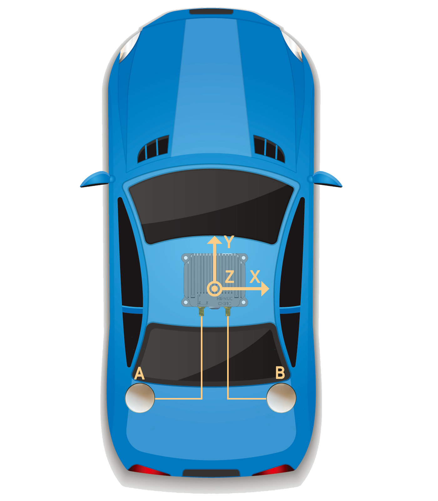
Example: to set the angle between the A→B vector and the vehicle forward direction (IMU +Y axis) to 90° (clockwise positive, as shown below), where antenna A relative to the IMU is X=-1.5,Y=-1.2,Z=-0.3 and antenna B relative to the IMU is X=1.5,Y=-1.2,Z=-0.3:
SETBASELINE ANTA -1.5,-1.2,-0.3
SETBASELINE ANTB  1.5,-1.2,-0.3
After installing/setting the antenna positions, power-cycle or reboot the module.
- After setting antenna parameters, use
LOG INSCONFIGto verify.- Integrated navigation also works without lever-arm compensation, but correct, valid compensation greatly improves position accuracy when turning after a GNSS outage.
SERIALCONFIG
Set the serial-port baud rate; 115200 / 460800 / 921600 are supported.
SERIALCONFIG <BAUD>
Example - set the current port to 115200: SERIALCONFIG 115200.
Output Data Protocol (RS232/422, Ethernet)
Overview
This product supports two output protocol families: ASCII and binary. ASCII messages use the NMEA format; binary messages use HiPNUC's custom binary format. The NMEA format follows NMEA 0183.
- Output latitude/longitude is referenced to antenna A.
- Antenna B is used only for dual-antenna heading and is unrelated to positioning.
Hardware Interfaces
- RS232 / RS422 / RS485: essentially all serial ports; both ends must use the same baud rate. Factory default is 115200.
- Ethernet: some products have Ethernet with an internal TCP/IP stack and DHCP client enabled by default. Connect the Ethernet port to a router LAN port on the same subnet as the PC; it obtains an IP automatically after connecting. Connect as a TCP client on default port 5944. Once connected, all commands and behavior are identical to the serial port.
Factory Default Output
By default this product outputs the binary HI81 protocol at 100 Hz.
NMEA Messages (ASCII)
The NMEA protocol starts with $, followed by the descriptor, ID and data fields. The data section ends with *, followed by a two-digit checksum and finally a carriage return + line feed (0x0D, 0x0A).
NMEA message format (ASCII structure):
$--<message-id>,<field>,<field>,...,<field>*<checksum><CR><LF>| Field | Description |
|---|---|
| $ | Start delimiter (ASCII 0x24). Marks the beginning of a message. |
| --- | Satellite-system class, used to distinguish BeiDou / GPS / combined output. BD - BeiDou GP - GPS GN - combined |
| message-id | Identifies the message type and function. Fixed 3-character ASCII; uppercase letters recommended. |
| , | Field delimiter (ASCII 0x2C). Separates multiple fields in a message. |
| data field | Each message can contain multiple fields separated by ,. Unless noted otherwise, only printable ASCII is allowed in fields. Field position within a message is determined by counting the , delimiters. |
| * | Checksum delimiter, between the data content and the checksum field. |
| checksum | The checksum is the byte-wise XOR of all characters between $ and * (exclusive). The high and low nibbles are each expressed as a hex ASCII character (0-9, A-F), high nibble first. |
<CR><LF> | Terminator (ASCII 0x0D, 0x0A). Marks the end of a message. |
NMEA Message List
| NMEA | Description | Source |
|---|---|---|
| GGA | Fix data, RTC time, fix quality, satellites in view | GNSS only |
| RMC | Recommended minimum positioning information | GNSS only |
| VTG | Current ground speed | GNSS only |
| SXT | Integrated-navigation information | Integrated nav |
GGA
Receiver time, position and fix-related data. Note: this sentence outputs the GNSS-only fix, not the integrated-navigation result.
$GPGGA,062134.00,2813.9908005,N,11252.6285300,E,1,28,0.5,83.684,M,-17.038,M,0.000,0000*60| ID | Example | Format | Description |
|---|---|---|---|
| 1 | $GPGGA | header | |
| 2 | 062134.00 | hhmmss.ss | UTC time |
| 3 | 2813.9908005 | ddmm.mmmm | Latitude, 28°13.9908005′, range 0°-90°. First two digits are degrees, the rest minutes. |
| 4 | N | - | Latitude direction N/S (N = north, S = south) |
| 5 | 11252.6285300 | ddmm.mmmm | Longitude, 112°52.6285300′, range 0°-180°. First three digits are degrees, the rest minutes. |
| 6 | E | - | Longitude direction E/W (E = east, W = west) |
| 7 | 1 | x | 0: invalid; 1: single-point; 2: pseudorange differential; 4: fixed; 5: float or PPP. |
| 8 | 28 | xx | Number of satellites used in the fix |
| 9 | 0.5 | x.x | HDOP: horizontal dilution of precision |
| 10 | 83.684 | x.xxx | Altitude |
| 11 | M | U | Altitude unit: m |
| 12 | -17.038 | x.x | Geoid undulation: difference between the WGS84 ellipsoidal height and altitude; "-" means the geoid is below the WGS84 ellipsoid. |
| 13 | M | U | Undulation unit: m |
| 14 | 0.000 | xxxx | Differential age, in s |
| 15 | 0000 | x.x | Differential station ID |
| 16 | 60 | hh | Checksum |
About the lat/long format in GGA:
Latitude: expressed as degrees and minutes (no seconds), as
ddmm.mmmm, whereddis degrees (two digits) andmm.mmmmis minutes (two integer digits and up to four decimals), followed by N (north) or S (south). Longitude: similar to latitude, but degrees are three digits, asdddmm.mmmm, followed by E (east) or W (west).Converting to decimal degrees: although GGA natively uses degrees and minutes, you sometimes need decimal degrees. The formula:
decimal degrees = degrees + (minutes / 60)
For example, converting 4807.038 to decimal degrees: 48 + (07.038 / 60) = 48.1173°
RMC
Recommended minimum navigation data. Note: this sentence outputs the GNSS-only fix, not the integrated-navigation result.
$GPRMC,020550.00,A,2813.9891299,N,11252.6278784,E,0.033,315.7,161117,0.0,E,A,V*4A| ID | Example | Format | Description |
|---|---|---|---|
| 1 | $GPRMC | header | Start delimiter + message ID |
| 2 | 020250.00 | hhmmss.ss | UTC time |
| 3 | A | x.x | Fix status: A = valid, V = invalid |
| 4 | 2813.9891299 | ddff.ff | Latitude, same format as GGA |
| 5 | N | - | Latitude direction, same as GGA |
| 6 | 11252.6278784 | dddff.ff | Longitude, same format as GGA |
| 7 | E | - | Longitude direction, same as GGA |
| 8 | 0.033 | x.x | Ground speed, in knots |
| 9 | 315.7 | x.x | Ground course, referenced to true north, clockwise (0°-360°) |
| 10 | 161117 | ddmmyy | Date (day, month, year) |
| 11 | 0.0 | x.x | Magnetic declination, in degrees |
| 12 | E | - | Declination direction |
| 13 | A | - | Mode indicator: N = invalid; A = autonomous; E = estimated; D = differential; M = manual input |
| 14 | V | - | S = Safe, C = Caution, U = Unsafe, V = Not valid |
| 15 | 4A | hh | Checksum |
VTG
Outputs ground-speed information.
$GPVTG,134.395,T,134.395,M,0.019,N,0.035,K,A*33| ID | Example | Format | Description |
|---|---|---|---|
| 1 | $GPVTG | header | |
| 2 | 134.395 | xxx.xxx | Ground course referenced to true north, 000-359.999° |
| 3 | T | U | True-north indicator |
| 4 | 134.395 | xxx.xxx | Ground course referenced to magnetic north, 000-359.999° |
| 5 | M | U | Magnetic-north indicator |
| 6 | 0.019 | xxx.xxx | Horizontal speed 000-999, in knots |
| 7 | N | U | Unit: N = knots |
| 8 | 0.035 | xxx.xxx | Horizontal speed 000-999, in km/h |
| 9 | K | U | Unit: K = km/h |
| 10 | A | U | A = autonomous; D = differential; E = estimated; M = manual input; N = invalid. |
| 11 | 33 | hh | Checksum |
SXT
Outputs integrated-navigation information.
$GPSXT,20230310090529.59,116.45784882,39.90572287,158.2289,359.87,-4.99,359.87,0.001,171.25,1,0,15,15,0.056,-0.040,0.017,-0.001,-0.000,0.002,8,0*43| ID | Example | Format | Description |
|---|---|---|---|
| 1 | $GPSXT | header | |
| 2 | 20230310090529.59 | yyyy/mm/dd/hh/mm/ss.ss | UTC time |
| 3 | 116.45784882 | ddd.dddddddd | Fused longitude (deg) |
| 4 | 39.90572287 | ddd.dddddddd | Fused latitude (deg) |
| 5 | 158.2289 | ddd.dddd | Fused altitude (m) |
| 6 | 359.87 | ddd.dd | Yaw (deg), 0-360° |
| 7 | -4.99 | ddd.dd | Pitch (deg), -90:90° |
| 8 | 359.87 | ddd.dd | Velocity course (deg) |
| 9 | 0.001 | ddd.ddd | Horizontal speed (m/s) |
| 10 | 171.25 | ddd.dd | Roll (deg), -180:180° |
| 11 | 1 | GNSS-only fix flag: 0 invalid; 1 single-point; 2 pseudorange differential; 4 fixed; 5 float/PPP. Relates to antenna A only, not B. | |
| 12 | 0 | GNSS-only heading flag: 4 fixed (heading valid); other values: heading not locked, invalid. Relates to antennas A and B; heading is meaningful only with a fixed solution (4). | |
| 13 | 15 | Satellites used by antenna A (positioning) | |
| 14 | 15 | Satellites used by antenna B (heading) | |
| 15 | 0.056 | X-axis angular rate (deg/s) | |
| 16 | -0.040 | Y-axis angular rate (deg/s) | |
| 17 | 0.017 | Z-axis angular rate (deg/s) | |
| 18 | -0.001 | ddd.ddd | East velocity (m/s) |
| 19 | -0.000 | ddd.ddd | North velocity (m/s) |
| 20 | 0.002 | ddd.ddd | Up velocity (m/s) |
| 21 | 8 | Integrated-navigation status: 0: invalid - no GNSS, cannot initialize position 1: aligning - position initialized, but some motion is needed to finish filter initialization and enter integrated navigation 3: navigating - integrated navigation engaged 6: inertial dead-reckoning - integrated navigation engaged but GNSS lost, in pure-inertial mode (tunnel, garage, etc.) | |
| 22 | antenna status | 0: A normal, B normal 1: A abnormal (not inserted, feeder open/short), B normal 2: A normal, B abnormal 3: A abnormal, B abnormal Valid only with our dedicated measurement antenna. | |
| 23 | 08 | hh | Checksum |
Binary Messages (HiPNUC)
This is HiPNUC's custom binary protocol. It can output all sensor information and is supported by products with UART (RS-232/TTL), USB and RS-485 interfaces. Default serial format is N-8-N-1 (8 data bits, 1 stop bit, no parity).
Frame Format
After power-up, the module outputs frame data at the default rate (100 Hz). The frame format:
| Field | Value | Length (bytes) | Description |
|---|---|---|---|
| Frame header | 0x5A | 1 | 0x5A |
| Frame type | 0xA5 | 1 | 0xA5 |
| Payload len | 1-512 | 2 | Length of the payload, LSB first. Counts the payload only (excludes header, type, length, CRC). |
| CRC | - | 2 | 16-bit CRC over all fields except CRC itself (header, type, length, payload). LSB first. |
| Payload | - | 1-512 | Data carried in one frame, made of several sub-packets. Each packet has a tag and data; the tag determines the data type and length. |
Payload Content
Integrated Navigation Data (HI81)
The payload is 104 bytes and contains all navigation information.
| Offset | Name | Type | Size (Byte) | Unit | Scale | Description |
|---|---|---|---|---|---|---|
| 0 | tag | uint8_t | 1 | - | - | Packet tag: 0x81 |
| 1 | status | uint16_t | 2 | - | - | Status word, reserved |
| 3 | ins_status | uint8_t | 1 | - | - | Integrated-navigation status: 0: invalid - no GNSS, cannot initialize position 1: aligning 3: navigating 6: inertial dead-reckoning (GNSS lost) |
| 4 | gpst_wn | uint16_t | 2 | week | 1 | GPS time, week |
| 6 | gpst_tow | uint32_t | 4 | s | 0.001 | GPS time, time of week |
| 10 | reserved | uint16_t | 2 | - | - | Reserved |
| 12 | gyr_b | int16_t*3 | 6 | rad/s | 0.001 | Body-frame angular rate: X, Y, Z (factory calibrated) |
| 18 | acc_b | int16_t*3 | 6 | m/s^(2) | 0.0048828 | Body-frame acceleration: X, Y, Z (factory calibrated) |
| 24 | mag_b | int16_t*3 | 6 | uT | 0.030517 | Body-frame magnetic field: X, Y, Z (factory calibrated) |
| 30 | air_pressure | int16_t | 2 | Pa | 1 | Air pressure + 100000 Pa: e.g. 2000 means 102000 Pa |
| 32 | od_speed | int16_t | 2 | m/s | 0.01 | Odometer speed (vehicle OBD-II speed) |
| 34 | temperature | int8_t | 1 | °C | 1 | System average temperature |
| 35 | utc_year | uint8_t | 1 | year | 1 | UTC year, e.g. 24 = 2024 |
| 36 | utc_mouth | uint8_t | 1 | month | 1 | UTC month |
| 37 | utc_day | uint8_t | 1 | day | 1 | UTC day |
| 38 | utc_hour | uint8_t | 1 | hour | 1 | UTC hour |
| 39 | utc_min | uint8_t | 1 | min | 1 | UTC minute |
| 40 | utc_sec | uint16_t | 2 | s | 0.001 | UTC second |
| 42 | roll | int16_t | 2 | deg | 0.01 | Integrated-nav roll, range -180:180 |
| 44 | pitch | int16_t | 2 | deg | 0.01 | Integrated-nav pitch, range -90:90 |
| 46 | yaw | uint16_t | 2 | deg | 0.01 | Integrated-nav yaw, range 0-360, north-to-east positive |
| 48 | quat | int16_t*4 | 8 | - | 0.0001 | Quaternion: W, X, Y, Z |
| 56 | ins_lon | int32_t | 4 | deg | 1e-7 | Fused longitude |
| 60 | ins_lat | int32_t | 4 | deg | 1e-7 | Fused latitude |
| 64 | ins_msl | int32_t | 4 | m | 0.001 | Fused altitude |
| 68 | pdop | uint8_t | 1 | - | 0.1 | GNSS position dilution of precision |
| 69 | hdop | uint8_t | 1 | - | 0.1 | GNSS horizontal dilution of precision |
| 70 | solq_pos | uint8_t | 1 | - | - | GNSS-only fix flag: 0 invalid; 1 single-point; 2 pseudorange differential; 4 fixed; 5 float/PPP. Antenna A only. |
| 71 | nv_pos | uint8_t | 1 | - | - | Satellites used for GNSS positioning |
| 72 | solq_heading | uint8_t | 1 | - | - | GNSS-only heading flag: 4 fixed (heading valid); other values: not locked. Relates to A and B; only fixed makes heading meaningful. |
| 73 | nv_heading | uint8_t | 1 | - | - | Satellites used for GNSS heading |
| 74 | diff_age | uint8_t | 1 | s | 1 | RTK differential age |
| 75 | undulation | int16_t | 2 | m | 0.01 | Geoid undulation |
| 77 | ant_status | uint8_t | 1 | - | - | Antenna status flag 0: A normal, B normal 1: A abnormal (not inserted, feeder open/short), B normal 2: A normal, B abnormal 3: A abnormal, B abnormal Valid only with our dedicated measurement antenna. |
| 78 | vel_enu | int16_t*3 | 6 | m/s | 0.01 | ENU velocity in the navigation frame (integrated-nav output) |
| 84 | acc_enu | int16_t*3 | 6 | m/s^(2) | 0.0048828 | ENU acceleration in the navigation frame (integrated-nav output) |
| 90 | reserved | int16_t | 2 | Reserved | ||
| 92 | reserved | int16_t | 2 | Reserved | ||
| 94 | reserved | int16_t | 2 | Reserved | ||
| 96 | reserved | int16_t | 2 | Reserved | ||
| 98 | reserved | - | 6 | - | - | Reserved |
CRC
16-bit CRC reference implementation:
/*
	currectCrc: previous crc value, set 0 if it's first section
	src: source stream data
	lengthInBytes: length
*/
static void crc16_update(uint16_t *currectCrc, const uint8_t *src, uint32_t lengthInBytes)
{
    uint32_t crc = *currectCrc;
    uint32_t j;
    for (j=0; j < lengthInBytes; ++j)
    {
        uint32_t i;
        uint32_t byte = src[j];
        crc ^= byte << 8;
        for (i = 0; i < 8; ++i)
        {
            uint32_t temp = crc << 1;
            if (crc & 0x8000)
            {
                temp ^= 0x1021;
            }
            crc = temp;
        }
    }
    *currectCrc = crc;
}
Data Protocol (CAN - SAE J1939)
The CAN interface supports both CANopen and SAE J1939. The module defaults to SAE J1939; contact technical support for a CANopen version. The default CAN baud rate is 500 Kbps.
SAE J1939 Protocol
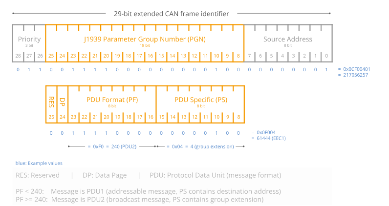
J1939 uses a 29-bit extended frame ID: 3 bits of priority, 1 reserved bit, an 8-bit page that defines its function via the PGN, with the first 8 of the lower 24 bits being the source address (SA), the middle 8 the specific PGN (describing the data function/content), and the last 8 the destination address (DA) or a further-refined PGN. This structure supports prioritized message transmission, a wide range of parameter-group identifiers, and source/destination addressing on the network.
| PGN | Description |
|---|---|
| Communication mode | Broadcast |
| Default interval | 100 ms |
| Data length | 8 bytes per PGN |
| PF (PDU format) | 0xFF |
| PS (PDU specific) | Extended PGN address (GE) when PF > 0xF0, otherwise the destination address (DA) |
| Priority | 3 |
| Default J1939 address | 0x08 |
| Data format | All frames use LSB (little-endian); unless noted, signed integers |
PGN Message List
PGN65296 (FF10) Latitude/Longitude
CANID=0x0CFF1008
| SPN name | SPN position (byte) | Description |
|---|---|---|
| Latitude | 0-3 | Unit: deg, scale: 0.0000001 |
| Longitude | 4-7 | Unit: deg, scale: 0.0000001 |
PGN65300 (FF14) Altitude and Differential Age
CANID=0x0CFF1408
| SPN name | SPN position (byte) | Description |
|---|---|---|
| Altitude | 0-3 | Unit: m, scale: 0.01 |
| UNDULATION | 4-5 | Unit: m, scale: 0.01 |
| Diff age | 6-7 | Unit: s, scale: 0.01 |
PGN65304 (FF18) Fix Status and Satellite Count
CANID=0x0CFF1808
| SPN name | SPN position (byte) | Description |
|---|---|---|
| GNSS-only fix quality | 0 | 0 invalid; 1 single-point; 2 pseudorange differential; 4 fixed; 5 float/PPP. |
| GNSS-only heading qual | 1 | 0 invalid; 4 fixed (only a fixed solution makes heading meaningful) |
| Positioning sat count | 2 | Satellites used for positioning |
| Heading sat count | 3 | Satellites used for heading |
| Integrated-nav status | 4 | 1: aligning, 3: navigating |
| Reserved | 5-7 | - |
PGN65318 (FF26) Velocity
CANID=0x0CFF2608
| SPN name | SPN position (byte) | Description |
|---|---|---|
| East velocity | 0-1 | Unit: m/s, scale: 0.01 |
| North velocity | 2-3 | Unit: m/s, scale: 0.01 |
| Up velocity | 4-5 | Unit: m/s, scale: 0.01 |
| Ground speed (E/N resultant magnitude) | 6-7 | Unit: m/s, scale: 0.01 |
PGN65327 (FF2F) Time
CANID=0x0CFF2F08
| SPN name | SPN position (byte) | Description |
|---|---|---|
| UTC year | 0 | 20 = 2020, and so on |
| UTC month | 1 | |
| UTC day | 2 | |
| UTC hour | 3 | |
| UTC min | 4 | |
| UTC sec | 5 | |
| UTC ms | 6-7 | Unit: ms, scale: 1 |
PGN65332 (FF34) Acceleration
CANID=0x0CFF3408
| SPN name | SPN position (byte) | Description |
|---|---|---|
| Accel X | 0-1 | Unit: G (1G = gravity), scale: 0.00048828 |
| Accel Y | 2-3 | Unit: G (1G = gravity), scale: 0.00048828 |
| Accel Z | 4-5 | Unit: G (1G = gravity), scale: 0.00048828 |
| Reserved | 6-7 | - |
PGN65335 (FF37) Angular Rate
CANID=0x0CFF3708
| SPN name | SPN position (byte) | Description |
|---|---|---|
| Rate X | 0-1 | Unit: deg/s, scale: 0.061035 |
| Rate Y | 2-3 | Unit: deg/s, scale: 0.061035 |
| Rate Z | 4-5 | Unit: deg/s, scale: 0.061035 |
| Reserved | 6-7 |
PGN65341 (FF3D) Integrated-Nav Attitude (Pitch/Roll)
CANID=0x0CFF3D08
| SPN name | SPN position (byte) | Description |
|---|---|---|
| Roll | 0-3 | Unit: °, scale: 0.001 |
| Pitch | 4-7 | Unit: °, scale: 0.001 |
PGN65345 (FF41) Integrated-Nav Attitude (Heading)
CANID=0x0CFF4108
| SPN name | SPN position (byte) | Description |
|---|---|---|
| Yaw | 0-3 | 0-360, unit: °, scale: 0.001 |
| Reserved | 4-7 |
PGN65347 (FF43) Temperature and Air Pressure
CANID=0x0CFF4308
| SPN name | SPN position (byte) | Description |
|---|---|---|
| Temperature | 0-1 | Unit: ℃, scale: 0.01 |
| Reserved | 2-3 | |
| Air pressure | 4-7 | Unit: Pa, scale: 0.01 |
Module Configuration (CAN)
Configuration Format
Host sends: ADDR + CMD + STATUS + VAL; device replies: ADDR + CMD + STATUS + VAL.
| Field | Size (Byte) | Description |
|---|---|---|
| ADDR | 2 | Register address |
| CMD | 1 | 0x06: write, 0x03: read |
| STATUS | 1 | Reserved |
| VAL | 4 | Value written or read |
Common Command Examples
| 29-bit CAN ext. frame ID | CAN data | Description | Notes |
|---|---|---|---|
| 0x0CEF08xx | 10 01 06 00 [VAL] | VAL: 4 bytes (LE) | PGN FF10 (lat/long) interval, ms, range 10-1000 |
| 0x0CEF08xx | 14 01 06 00 [VAL] | VAL: 4 bytes | PGN FF14 (altitude & diff age) interval, ms, range 10-1000 |
| 0x0CEF08xx | 18 01 06 00 [VAL] | VAL: 4 bytes | PGN FF18 (fix status & sats) interval, ms, range 10-1000 |
| 0x0CEF08xx | 2F 01 06 00 [VAL] | VAL: 4 bytes | PGN FF2F (time) interval, ms, range 10-1000 |
| 0x0CEF08xx | 34 01 06 00 [VAL] | VAL: 4 bytes | PGN FF34 (acceleration) interval, ms, range 10-1000 |
| 0x0CEF08xx | 37 01 06 00 [VAL] | VAL: 4 bytes | PGN FF37 (angular rate) interval, ms, range 10-1000 |
| 0x0CEF08xx | 3D 01 06 00 [VAL] | VAL: 4 bytes | PGN FF3D (pitch/roll) interval, ms, range 10-1000 |
| 0x0CEF08xx | 41 01 06 00 [VAL] | VAL: 4 bytes | PGN FF41 (heading) interval, ms, range 10-1000 |
| 0x0CEF08xx | 43 01 06 00 [VAL] | VAL: 4 bytes | PGN FF43 (temp & pressure) interval, ms, range 10-1000 |
| 0x0CEF08xx | 9A 00 06 00 [VAL] | VAL: 4 bytes | Set baud rate (saved, effective on reset): 0:1000K, 1:800K, 2:500K, 3:250K, 4:125K |
| 0x0CEF08xx | 9C 00 06 00 [VAL] | VAL: 4 bytes | J1939 device ID, 1-64 (default 8). Caution: changing the ID also requires updating the destination address in all J1939 frame IDs. |
| 0x0CEF08xx | 00 00 06 00 00 00 00 00 | - | Save all configuration to Flash |
| 0x0CEF08xx | 00 00 06 00 01 00 00 00 | - | Restore factory defaults |
| 0x0CEF08xx | 00 00 06 00 FF 00 00 00 | - | Reset |
xxin the ID field: the J1939 source address, any byte.xxin the data field: any byte.Example: ID=0x0CEF0855, DATA = 37 01 06 00 64 00 00 00 sets PGN FF37 to a 100 ms period (10 Hz).
Firmware Upgrade
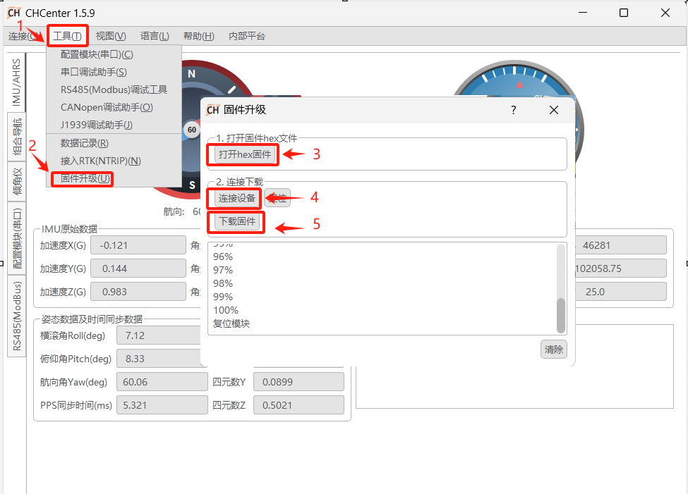
This product supports firmware upgrades. Use the CHCenter host software and follow the steps below; request the firmware file (.hex) from our technical support.
Technical Support
New product and document information is available via our website and WeChat official account. WeChat: