Command and Programming Manual
Rev 1.7.1
Applicable to CH0x0/HI02/04/05/06/14/50/90/70 series (shared programming interface)
This manual is based on firmware version: 1.7.1
Actual feature availability depends on the specific product model, firmware version, and delivered configuration.
Manual Version Notes (Important)
Because there are subtle differences in commands, performance, and features between firmware versions, please choose the corresponding user manual based on the firmware version of your product:
| Applicable firmware version | Matching user manual version | Download link |
|---|---|---|
| 1.7.1 | 1.7.1 | This manual |
| 1.5.5 - 1.7.0 | 1.3.0 | imu_cum_cn_150_170.pdf |
Module Configuration Overview
Before using the product, please read this chapter carefully and determine whether user configuration is required based on your actual use case.
Operating Mode Configuration - AHRS / 9-Axis Mode
⚠️ Warning In robotic applications and indoor environments, the AHRS (9-axis) mode is easily disturbed by ambient magnetic fields or magnetic fields generated by motors, which can introduce errors into the heading angle.
In open environments without magnetic interference (e.g., outdoor UAV operations), magnetometer-aided mode may be used. Before use, you need to:
- Configure the module to magnetometer-aided mode;
- Perform magnetic calibration (see the "Magnetic Calibration" chapter).
Synchronous Input - SYNC_IN / PPS
The module's synchronization-related features rely on the SYNC_IN/PPS pin, mainly including the following two categories:
- SYNC_IN data trigger
- PPS (pulse-per-second) input for UTC time synchronization
SYNC_IN Data Trigger
Some products provide a synchronization input pin (SYNC_IN/PPS) that can be used to trigger data output by external pulses. Leave the pin floating or grounded when not in use. Working principle: when the output protocol is configured to the ONMARK trigger mode (see the LOG command), the module outputs one frame of data each time a rising edge is detected on the SYNC_IN pin.
Application scenario: mainly used to receive high-precision pulses generated by the host controller or an external clock source to trigger synchronous IMU data output.
PPS Standard Pulse Input
This function uses the (SYNC_IN/PPS) pin to receive the GPS PPS pulse signal, combined with time messages received from the UART, to provide precise UTC time synchronization for the IMU. When the module detects a valid PPS rising edge and receives a matching time message via the UART, its internal clock automatically aligns to UTC integer seconds.
1. Timing and Signal Requirements
To ensure reliable time synchronization, the PPS pulse and the UART time message must satisfy the following timing relationship:
gantt
    title PPS and UART time-message timing (t0-t3)
    dateFormat  X
    axisFormat  %s

    section SYNC_IN/PPS
    t1 (pulse width) :active, p1, 0, 50
    t0 (period) :p2, 0, 1000

    section UART time message
    t3 (delay) :crit, d1, 0, 150
    t2 (transmission time) :done, r1, 150, 250
Parameter description:
| Parameter | Description | Valid range | Recommended value |
|---|---|---|---|
| t0 | Interval between two adjacent PPS rising edges | 990 ms ~ 1010 ms | 1000 ms |
| t1 | PPS high-level duration (pulse width) | 1 ms ~ 100 ms | 10 ms ~ 50 ms |
| t2 | Transmission time of the time message | Depends on baud rate | - |
| t3 | Delay between start of the time message and the PPS rising edge | -200 ms ~ +200 ms | 0 ms ~ 100 ms |
⚠️ Core requirement: The time message used for synchronization must be sent within 200 ms before or after the PPS rising edge (i.e.,
); otherwise the IMU will not be able to match UTC time correctly.
2. Hardware and Interface Requirements
- Hardware pin (SYNC_IN/PPS):
- Trigger edge: rising edge;
- Logic level: high level ≤ 5 V (TTL/CMOS compatible);
- UART data (RX):
- Message rate: 1~10 Hz (recommended: 1 Hz);
- Baud rate: must exactly match the IMU UART setting;
- Supported protocols: only standard NMEA
RMCorGGAsentences.
3. Time Message Example (GPRMC)
$GPRMC,235952.00,A,3112.5000,N,12127.5000,E,0.0,0.0,141125,0.0,E,A*3BAfter time synchronization, the timestamp (uint32_t) in each data frame indicates the milliseconds elapsed since UTC 00:00:00 of the current day.
| Parameter | Value |
|---|---|
| Range | 0~86,399,999 ms |
| Range of time | 00:00:00.000 to 23:59:59.999 |
| Resolution | 1 ms |
Timestamp conversion examples and C code:
| Timestamp (ms) | UTC time |
|---|---|
| 0 | 00:00:00.000 |
| 3661000 | 01:01:01.000 |
| 43200000 | 12:00:00.000 |
| 86399999 | 23:59:59.999 |
// Time conversion formula:
// Hours = timestamp / 3600000
// Minutes = (timestamp % 3600000) / 60000
// Seconds = (timestamp % 60000) / 1000
// Milliseconds = timestamp % 1000

void ms_to_utc_time(uint32_t total_ms, char *utc_time, int buf_size)
{
    // Calculate hours, minutes, seconds and milliseconds
    uint32_t total_seconds = total_ms / 1000;
    uint32_t ms_part = total_ms % 1000;

    uint8_t hours = (total_seconds / 3600) % 24;
    uint8_t minutes = (total_seconds % 3600) / 60;
    uint8_t seconds = total_seconds % 60;

    // Format as hh:mm:ss.sss
    snprintf(utc_time, buf_size, "%02d:%02d:%02d.%03d",
             hours, minutes, seconds, ms_part);
}
📝 Notes
- The timestamp does not contain date information; it only represents UTC time of the current day (milliseconds since 00:00:00).
- It does not include time-zone information and is interpreted as UTC+0; for local time, the host should add the time-zone offset.
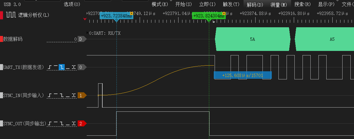
Synchronous Output - SOUT
SOUT is the module's synchronous output pin. It stays low (idle) when no data is being transmitted; before a frame starts to transmit, a high pulse is emitted, and data transmission begins immediately after the falling edge of the pulse.
The SOUT pin also supports frequency division, allowing the synchronization pulse to be output at a configurable divisor. This can be used to trigger lower-rate devices such as cameras for tight time synchronization. See CONFIG PMUX2 DIV in the "Module Configuration" chapter for divider configuration.
Vessel Wave-Compensated Displacement Output - Heave, Surge, Sway
This product can measure the periodic vessel motion induced by sea waves (heave, surge, sway) and provide high-precision real-time three-axis wave motion information:
| Motion axis | Description | Output data |
|---|---|---|
| Heave | Vertical heave | Vertical displacement, vertical velocity, vertical displacement period |
| Surge | Longitudinal surge | Longitudinal displacement, longitudinal velocity, longitudinal displacement period |
| Sway | Lateral sway | Lateral displacement, lateral velocity, lateral displacement period |
Application scenarios:
- Vessel dynamic monitoring and attitude control
- Offshore engineering motion compensation (lifting, docking)
- Wave characterization and statistical analysis
- Offshore platform stability analysis
- Dynamic positioning (DP) system assistance
Usage Limitations
⚠️ Important limitations
Only applicable to periodic reciprocating motion.
The following situations generally cannot be measured accurately:
- Motions with very long periods (>30 s)
- One-directional linear motion
- Step-type displacement
Zero-mean assumption: the algorithm assumes the long-term average of displacement is 0.
Initialization time: a steady 5~20 wave cycles are required for initialization to obtain correct results.
Frequency response range: typical wave periods are 3~20 s; accuracy degrades outside this range.
📝 Product compatibility Only HI7x/HI9x series products support this feature. See "Product Feature Support Matrix".
Product Feature Support Matrix
The following table provides an overview of common feature support across product families. Actual feature availability depends on the specific product model, firmware version, and delivered configuration.
Features not listed in the table do not imply they are necessarily supported or enabled by default; for a specific model, please refer to the delivery notes.
| Model / Command | HI02 | HI05/06 | CH0x0, HI04/12/13/14 | HI50 | HI7x/9x |
|---|---|---|---|---|---|
| Magnetometer aiding / mag calibration | ✗ | ✅ | ✅ | ✗ | ✅ |
| User attitude calibration | ✗ | ✅ | ✅ | ✅ | ✅ |
| IO pin multiplexing (PMUX) | ✗ | ✅ | ✅ | ✗ | ✗ |
| CAN communication interface | ✗ | ✅ | ✅ | ✅ | ✅ |
| Vessel heave output | ✗ | ✗ | ✗ | ✗ | ✅ |
| Inclinometer output | ✗ | ✗ | ✗ | ✅ | ✗ |
Module Configuration Commands (ASCII)
Module configuration uses ASCII string commands sent over the UART. Each command must end with carriage-return + line-feed \r\n (similar to AT commands).
For any operation that modifies parameters, the recommended procedure is: "Send the configuration command -> execute SAVECONFIG -> reset or power cycle -> verify again". Query-type commands and some communication-control commands may take effect immediately in the current session, but the recommended configuration flow above still applies.
📝 Configuration semantics
- Whether a command takes effect immediately is specified in each command description;
- For configurations that must persist, execute
SAVECONFIGand then reset or power cycle to confirm;- Communication-parameter commands may switch immediately on the current interface;
- Restore-type commands may automatically save and trigger a reset.
The following table lists common externally-facing configuration commands. Additional commands for compatibility, debugging, or customization purposes depend on the actual delivered configuration.
Command Overview
| Command | Function | Remarks |
|---|---|---|
| REBOOT | Reset the module | Equivalent to a power cycle |
| SAVECONFIG | Save all configuration parameters | Takes effect immediately |
| SERIALCONFIG | Configure UART baud rate | Takes effect immediately |
| CONFIG | Configure module parameters and modes | Save and reset for effect |
| LOG | Query module info or configure output | Takes effect immediately |
| FRESET | Restore factory defaults | Takes effect immediately |
Command Details
REBOOT
Reset the module. Execute REBOOT BL to reset into Bootloader mode. Examples: REBOOT, REBOOT BL
SAVECONFIG
Save all user configurations to flash. Example: SAVECONFIG
SERIALCONFIG
Set the current UART baud rate.
Format: SERIALCONFIG <BAUD>
Parameters:
BAUD: target baud rate. Supported values:4800,9600,19200,38400,57600,115200,230400,256000,460800,921600
Example:
SERIALCONFIG 115200- set the current UART to 115200 baud
⚠️ Important This command takes effect immediately. After execution, switch to the new baud rate to continue communicating with the module.
CONFIG
Used to configure module parameters and operating modes. For any CONFIG setting that needs to persist, run SAVECONFIG after the change and confirm the result after a reset or power cycle.
Operating Mode Configuration
Operating mode configuration: 6-axis or 9-axis (magnetometer-aided) mode. Format: CONFIG ATT MODE <VAL>. The most common modes are listed below; other industry-specific or customized modes depend on the actual delivered configuration.
Examples:
CONFIG ATT MODE 0- configure the module to VRU (6-axis) modeCONFIG ATT MODE 1- configure the module to AHRS (9-axis) modeCONFIG ATT MODE 4- humanoid robot dedicated mode
User Attitude Calibration
Used to perform attitude zero-point related operations. Format: CONFIG ATT RST <VAL>. The device must remain stationary while executing this command; otherwise large calibration errors may be introduced.
Examples:
CONFIG ATT RST 1- Heading reset: zero the current heading angleCONFIG ATT RST 2- Set relative zero: zero the current Pitch and Roll anglesCONFIG ATT RST 3- Auto-level: only valid when the device is close to horizontal. Defined as:- If the current Pitch/Roll is close to 0° (placed horizontally right-side up), auto-calibrate to Pitch=0°, Roll=0°;
- If the current Pitch is close to 0° and Roll is close to 180° (placed horizontally upside-down), auto-calibrate to Pitch=0°, Roll=180°;
- The "close to" threshold is Pitch and Roll both less than 5°.
CONFIG ATT RST 5- Cancel auto-level: clear relative Pitch and Roll angles and restore absolute angles
Mounting Orientation Setting
Used to modify the module's mounting orientation, such as horizontal mounting, vertical mounting, upside-down, or forward-facing installation for integrated navigation. Save and reset to confirm such settings; no need to resend at every power-up.
Format: CONFIG IMU URFR <CODE>
Parameters:
CODE: 2- to 3-digit orientation code, representing the mounting direction of the user coordinate system relative to the sensor coordinate system.- The code is written as
ABC, where:Aindicates which direction in the sensor frame the user-frameXaxis points toBindicates which direction in the sensor frame the user-frameYaxis points toCindicates which direction in the sensor frame the user-frameZaxis points to
- Each digit has the following meaning:
| Digit | Direction |
|---|---|
0 | +X |
1 | -X |
2 | +Y |
3 | -Y |
4 | +Z |
5 | -Z |
Notes:
24is equivalent to024, meaning user frameX=+X,Y=+Y,Z=+Z. For the product's default mounting, this can be understood asX points right, Y points forward, Z points up.- This command uses spaces to separate parameters. The correct form is
CONFIG IMU URFR 24, notCONFIG IMU URFR=24. - The current configuration query result is displayed in the form
URFR=<CODE>. - If the user coordinate system is defined as right/forward/up of the body, you can directly choose the corresponding code from the table below based on the installation orientation.
Complete configuration examples (24 valid right-handed combinations):
- The table is presented in "Equivalent installation description" form (consistent with the host UI dropdown): direction of
IMU X/Y/ZinBody(B). - The
URFRencoding itself is still three digitsABC(with the right-handed constraintX × Y = Z); the 2-digit display value is equivalent to the 3-digit value with a leading zero (e.g.,24=024).
| Equivalent installation description (IMU axes in Body(B)) | Configuration command | Notes |
|---|---|---|
IMU X points right, IMU Y points forward, IMU Z points up | CONFIG IMU URFR 24 | Default horizontal mounting; full code is 024. |
IMU X points right, IMU Y points backward, IMU Z points down | CONFIG IMU URFR 35 | Common upside-down mounting (rotated about X relative to default); full code is 035. |
IMU X points right, IMU Y points down, IMU Z points forward | CONFIG IMU URFR 43 | Common side mounting; matches "Right + Down" in the host UI. |
IMU X points right, IMU Y points up, IMU Z points backward | CONFIG IMU URFR 52 | Common side mounting; matches "Right + Up" in the host UI. |
IMU X points left, IMU Y points forward, IMU Z points down | CONFIG IMU URFR 125 | Inverted combo with X reversed and Z pointing down. |
IMU X points left, IMU Y points backward, IMU Z points up | CONFIG IMU URFR 134 | Both X/Y reversed with Z up; common when orientation is reversed. |
IMU X points left, IMU Y points up, IMU Z points forward | CONFIG IMU URFR 142 | Left-facing vertical mounting with Y pointing up. |
IMU X points left, IMU Y points down, IMU Z points backward | CONFIG IMU URFR 153 | Left-facing vertical mounting with Y pointing down. |
IMU X points forward, IMU Y points right, IMU Z points down | CONFIG IMU URFR 205 | Forward-facing mounting, suitable when X is aligned with the vehicle heading. |
IMU X points backward, IMU Y points right, IMU Z points up | CONFIG IMU URFR 214 | Backward-facing mounting; Y still points right. |
IMU X points up, IMU Y points right, IMU Z points forward | CONFIG IMU URFR 240 | Vertical mounting with X up and Y right. |
IMU X points down, IMU Y points right, IMU Z points backward | CONFIG IMU URFR 251 | Vertical mounting with X down and Y right. |
IMU X points forward, IMU Y points left, IMU Z points up | CONFIG IMU URFR 304 | Forward-facing mounting with Y changed to left. |
IMU X points backward, IMU Y points left, IMU Z points down | CONFIG IMU URFR 315 | Backward-facing upside-down mounting; both X/Y reversed. |
IMU X points down, IMU Y points left, IMU Z points forward | CONFIG IMU URFR 341 | Left-facing vertical mounting with X down. |
IMU X points up, IMU Y points left, IMU Z points backward | CONFIG IMU URFR 350 | Left-facing vertical mounting with X up. |
IMU X points forward, IMU Y points up, IMU Z points right | CONFIG IMU URFR 402 | Forward-facing vertical mounting with Y up and Z right. |
IMU X points backward, IMU Y points down, IMU Z points right | CONFIG IMU URFR 413 | Backward-facing vertical mounting with Y down and Z right. |
IMU X points down, IMU Y points forward, IMU Z points right | CONFIG IMU URFR 421 | Vertical mounting with X down and Z right. |
IMU X points up, IMU Y points backward, IMU Z points right | CONFIG IMU URFR 430 | Vertical mounting with X up and Z right. |
IMU X points forward, IMU Y points down, IMU Z points left | CONFIG IMU URFR 503 | Forward-facing vertical mounting with Y down and Z left. |
IMU X points backward, IMU Y points up, IMU Z points left | CONFIG IMU URFR 512 | Backward-facing vertical mounting with Y up and Z left. |
IMU X points up, IMU Y points forward, IMU Z points left | CONFIG IMU URFR 520 | Common vertical mounting with X up and Z left. |
IMU X points down, IMU Y points backward, IMU Z points left | CONFIG IMU URFR 531 | Common vertical mounting with X down and Z left. |
Multi-Function IO Multiplexing Configuration
The module provides multiple multi-function pins (IOx). Each IO pin has a default multiplexing function and can also be remapped to other functions via software. Format: CONFIG <PMUX> <IO>.
Parameters:
PMUX: multiplexing function ID (PMUX1~PMUX3)IO: target pin ID (IO1~IO5)
| Function | Name | Dir | Description | Default IO |
|---|---|---|---|---|
| PMUX1 | SIN/PPS | I | Sync pulse input (SIN/PPS): input pin, see "Synchronous Input/Output" | IO1 |
| PMUX2 | SOUT | O | Low when no data is being transmitted (idle); before a frame starts to be sent, a high pulse is emitted, and data transmission begins immediately after the falling edge of the pulse | IO2 |
| PMUX3 | LED | O | Operating-status indicator output | IO5 |
Examples:
CONFIG PMUX3 IO2- assign IO2 to the LED (PMUX3) functionCONFIG PMUX2 IO1- assign IO1 to the sync output (PMUX2) function
📝 Note Not all IO pins are physically exposed on every product. See the corresponding product user manual for detailed hardware resources.
SOUT (PMUX2) Sync-Output Divider
The SOUT sync output supports frequency division, which can be used to trigger lower-rate fusion sensors such as cameras. Format: CONFIG PMUX2 DIV <N>.
Parameters:
N: divider, range1~1000, default1(no division)
Example:
CONFIG PMUX2 DIV 5- set the SOUT divider to 5. If the data output rate is 100 Hz, the SOUT pulse output frequency is 20 Hz.
Magnetic Calibration
Start a manual magnetic calibration: CONFIG MCAL START. After issuing this command, the module starts the calibration procedure and completes it automatically based on the spatial magnetic-field distribution; no explicit stop command is needed. During calibration, slowly rotate the module in place and ensure that any objects rigidly attached to it (PCB, housing, robot, etc.) maintain their relative positions. See the "Magnetic Calibration" chapter for details.
After issuing the start command, you can query calibration status with LOG MCAL STAT. Example response:
STAT=1
PROGRESS=8
OKSTAT: current magnetic calibration state.0= idle,1= calibrating,3= calibration complete,4= calibration failedPROGRESS: current calibration progress, range0~100
📝 Important The magnetic calibration command requires firmware version ≥ 1.7.0.
Coordinate System Definition
The module uses the East-North-Up (ENU) coordinate system by default. You can switch the world coordinate system using the following commands:
CONFIG IMU COORD 0- set the world frame to East-North-Up (ENU)CONFIG IMU COORD 4- set the world frame to North-West-Up (NWU)
User-Level Gyroscope Calibration
This command is used to manually calibrate the gyroscope Z-axis scale factor. When properly executed, it can improve heading accuracy (after calibration, the scale-factor error is within 0.1%). Suitable for AGVs, large horizontally-moving robots, and other applications with high long-term heading-accuracy requirements. Format: CONFIG USRCAL START <ANGLE>.
Parameters:
ANGLE: calibration angle, range720~1800°(2~5 turns). More turns reduce statistical error, but uniform rotation speed must be maintained.
Examples:
- Preparation: place the module (together with the rigidly attached platform such as a robot) on a flat horizontal surface, ensure stable ambient temperature, and avoid strong vibration.
- Send the start command: e.g.,
CONFIG USRCAL START 720- start 720° (2 turns) calibration. - Perform the calibration motion: rotate horizontally by the angle set in
<ANGLE>at 20~100 deg/s (about 5~20 s per turn). The rotation direction can be either clockwise or counterclockwise. Maintain uniform speed throughout the rotation; avoid pauses, sudden acceleration, or deceleration. - Send the stop command: when the rotation is complete and the actual rotation angle is within ±5° of the
<ANGLE>setpoint, sendCONFIG USRCAL STOPto finish the calibration. The module returnsOKon success orERRon failure.
Common causes of calibration failure:
| Failure cause | Description |
|---|---|
| Non-standard rotation | Ensure the module is placed horizontally and stably |
| Improper operation | Rotation too fast or too slow, mid-way pauses |
| Environmental disturbance | Avoid operating near vibrating equipment, e.g., excessive motor vibration |
| Errors persist or worsen after calibration | Most likely due to non-standard rotation. Calibration is a precise process: if the specified rotation is 720° but the actual rotation is 725°, the scale factor will be erroneously calibrated as 5/720 = 0.6%, far exceeding the factory accuracy |
LOG
Enable/Disable Data Output
LOG ENABLE- globally enable data frame outputLOG DISABLE- globally disable data frame output
Module Version Information
LOG VERSION - query and print firmware version information
Display UART Configuration
LOG COMCONFIG - print UART and output protocol configuration
Set Output Frame Type and Rate
Format: LOG <MSG> <TYPE> <VALUE>
Parameters:
MSG: data frame type. Common types includeHI91,HI81,HI83,GGA,RMC,SXT, etc. Available types depend on the specific product and current UART configuration.TYPE: output trigger mode, supportsONTIME(periodic output) andONMARK(sync-pulse trigger or software trigger).VALUE: whenTYPE=ONTIME, the output period in seconds. Range:0.001(1 kHz) ~1(1 Hz);0disables periodic output. WhenTYPE=ONMARK,1means trigger onSYNC_IN/PPSpulse, andONCEtriggers one output manually.
Examples:
LOG HI91 ONTIME 0.01- set theHI91output period on the current UART to0.01 s(100 Hz)LOG HI91 ONTIME 0.05- set theHI91output period on the current UART to0.05 s(20 Hz)LOG HI91 ONTIME 0- disableHI91outputLOG HI91 ONMARK 1- configure theHI91frame on the current UART to be triggered by theSYNC_IN/PPSpinLOG HI91 ONMARK ONCE- trigger oneHI91output manually (same effect as oneSYNC_IN/PPSpulse)
HI83 Variable-Length Frame Configuration
HI83 is a variable-length binary output frame, suitable for applications that need to simultaneously output IMU, attitude, time, GNSS, or integrated navigation data while controlling frame length on demand. The HI83 payload is determined by data_bitmap: each bit of data_bitmap corresponds to one data segment; setting the bit to 1 enables that segment, and 0 disables it. The data segments are arranged in the frame from low bit to high bit.
Bitmap configuration format: LOG HI83 MAP <BITMAP>
<BITMAP>can be expressed in hex or decimal, e.g.,0x000000FF;- For the meaning of each bit, see the "Variable-Length Protocol (HI83)" section below;
- The default HI83 bitmap is
0x000000FF.
Common configuration examples:
| Command | Description |
|---|---|
LOG HI83 MAP 0x000000FF | Default HI83 fields: acceleration, angular velocity, magnetic field, Euler angles, quaternion, system time, UTC, barometric pressure |
LOG HI83 MAP 0x0000001F | IMU + basic attitude: acceleration, angular velocity, magnetic field, Euler angles, quaternion |
LOG HI83 ONTIME 0.01 | Set the HI83 output period on the current UART to 0.01 s (100 Hz) |
LOG HI83 ONTIME 0 | Disable periodic HI83 output on the current UART |
⚠️ Baud rate notes When the output rate is high (e.g., 500 Hz), the default
115200baud rate may not provide sufficient bandwidth. In that case, increase the module baud rate to a higher value (e.g.,921600) to ensure stable data output.
FRESET
Restore the module's default user configuration. After execution, the module automatically saves and resets — use with caution. Some calibration-related parameters may be retained, depending on current firmware behavior. Example: FRESET
RS-232/TTL/USB Data Protocol (Binary)
RS-232, UART-TTL, and USB (virtual COM) are stream-style serial interfaces that support Hipnuc's proprietary binary protocol.
Data Frame Format
| Field | Value | Length (bytes) | Description |
|---|---|---|---|
| SOF | 5A A5 | 2 | Start-of-frame sync word |
| LEN | 1-4096 | 2 | Payload length, LSB first (does not include header, type, length, or CRC fields) |
| CRC | - | 2 | 16-bit CRC over the header, length, and payload (excludes the CRC field itself) |
| Payload | - | 1-4096 | Frame payload, composed of one or more sub-packets. Each sub-packet has a tag and data part, where the tag determines the data type and length. |
Factory Default Output
Default output: floating-point IMU data frame (HI91).
Payload Content
Floating-Point IMU Data Frame (HI91)
The payload is 76 bytes and includes module ID, temperature, raw IMU data, magnetic field, barometric pressure, and fused attitude data.
| Offset | Name | Type | Size (bytes) | Unit | Scale | Description |
|---|---|---|---|---|---|---|
| 0 | tag | uint8_t | 1 | - | - | Data tag: 0x91 |
| 1 | main_status | uint16_t | 2 | - | - | Status word, see MAIN_STATUS description |
| 3 | temperature | int8_t | 1 | °C | 1 | Module average temperature |
| 4 | air_pressure | float | 4 | Pa | 1 | Barometric pressure |
| 8 | system_time | uint32_t | 4 | ms | 1 | When GPS time is not synchronized, this field is a local timestamp (milliseconds since power-up); when GPS time is synchronized, this field is aligned to UTC milliseconds of the current day |
| 12 | acc_b | float | 4×3 | G | 1 | Factory-calibrated acceleration, XYZ order. 1 G = 1× standard gravity (~9.8 m/s²) |
| 24 | gyr_b | float | 4×3 | deg/s | 1 | Factory-calibrated angular velocity, XYZ order |
| 36 | mag_b | float | 4×3 | μT | 1 | Magnetic field strength, XYZ order |
| 48 | roll | float | 4 | deg | 1 | Roll angle |
| 52 | pitch | float | 4 | deg | 1 | Pitch angle |
| 56 | yaw | float | 4 | deg | 1 | Heading angle |
| 60 | quat | float | 4×4 | - | - | Node quaternion set, WXYZ order |
Variable-Length Protocol (HI83)
The data carried in this protocol is configurable; different combinations can be output by data_bitmap, and the frame size changes accordingly.
| Offset | Name | Type | Size (bytes) | Unit | Scale | Description |
|---|---|---|---|---|---|---|
| 0 | tag | uint8_t | 1 | - | - | Data tag: 0x83 |
| 1 | main_status | uint16_t | 2 | - | - | Status word, see MAIN_STATUS description |
| 3 | ins_status | uint8_t | 1 | - | - | Integrated navigation solution status (only for integrated-navigation products): 0: Solution invalid - no GNSS info, cannot initialize position 1: Aligning - position initialized, but speed is required to complete the integrated-navigation filter initialization to enter the integrated-navigation state 3: Integrated navigation - currently in integrated-navigation state 6: Inertial dead-reckoning - currently in integrated-navigation state but GNSS is lost; pure-inertial mode (tunnel, parking garage, etc.) |
| 4 | data_bitmap | uint32_t | 4 | - | - | Bitmap of carried data segments, configurable. Each bit corresponds to one data type; segments are arranged from the lowest bit to the highest |
| 8 | - | - | 1-512 | - | - | Subsequent payload defined by data_bitmap. |
data_bitmap Bits and Data Segments
| data_bitmap bit | Name | Type | Size | Unit | Scale | Description |
|---|---|---|---|---|---|---|
| 0 | acc_b | float | 4x3 | m/s^(2) | 1 | IMU body-frame, factory-calibrated acceleration, order: XYZ |
| 1 | gyr_b | float | 4x3 | rad/s | 1 | IMU body-frame, factory-calibrated angular velocity, order: XYZ |
| 2 | mag_b | float | 4x3 | μT | 1 | IMU body-frame, calibrated magnetic field, order: XYZ |
| 3 | rpy | float | 4x3 | deg | 1 | Attitude angles (Euler angles), order: roll, range: -180 - 180 pitch, range: -90 - 90 yaw, range: -180 - 180, counterclockwise positive |
| 4 | quat | float | 4x4 | - | 1 | Node quaternion set, WXYZ order |
| 5 | system_time_us | uint64_t | 8 | us | 1 | Local high-resolution timestamp, microseconds elapsed since power-up, incrementing by 1 every 1 us |
| 6 | utc | - | 8 | - | - | UTC time, 8 bytes total: year: 1 byte, e.g., 24 represents 2024 month: 1 byte day: 1 byte hour: 1 byte minute: 1 byte seconds: 2 bytes, unit 1 ms, e.g., 12 s is encoded as 12000 reserved: 1 byte |
| 7 | air_pressure | float | 4 | Pa | 1 | Barometric pressure |
| 8 | temperature | float | 4 | ℃ | 1 | Module average temperature |
| 9 | inclination | float | 4x3 | deg | 1 | Inclinometer output, order: about X axis, about Y axis, about Z axis |
| 10 | heave_surge_sway | float | 4x3 | m | 1 | Vessel heave-surge-sway displacement, order: heave, surge, sway |
| 11 | heave_surge_sway_frq | float | 4x3 | Hz | 1 | Vessel heave-surge-sway frequency, order: heave, surge, sway |
| 12 | vel_enu | float | 4x3 | m/s | 1 | East-North-Up velocity in the navigation frame, integrated-navigation output |
| 13 | acc_enu | float | 4x3 | m/s^(2) | 1 | East-North-Up acceleration in the navigation frame, integrated-navigation output |
| 14 | ins_lon_lat_msl | double | 8x3 | - | 1 | Fused longitude/latitude from integrated navigation, order: longitude (deg), latitude (deg), MSL altitude (m) |
| 15 | gnss_quality_nv | - | 4 | - | - | GNSS solution status group, 4 bytes: solq_pos: 1 byte, position solution status nv_pos: 1 byte, number of satellites used for position solq_heading: 1 byte, heading solution status nv_heading: 1 byte, number of satellites used for heading |
| 16 | od_speed | float | 4 | m/s | - | External odometer sensor speed |
| 17 | undulation | float | 4 | m | Geoid undulation | |
| 18 | diff_age | float | 4 | s | RTK differential age | |
| 19 | node_info | - | 4 | - | Device version and ID:node_id: 1 byte, node ID identical to CAN ID, range 1~127reserved: 3 bytes | |
| 20-24 | Reserved | |||||
| 25 | event_counter | uint32_t | 4x16 | - | 1 | Internal measurement event counters. Common order: gravity, mag, gnss_pos, gnss_vel, dual_heading, nhc, zupt, zaru, zihr, od; the rest are reserved |
| 26 | kf_acc_bias | float | 4x3 | m/s^(2) | 1 | Accelerometer bias estimated by the integrated-navigation KF, order: XYZ |
| 27 | kf_gyr_bias | float | 4x3 | rad/s | 1 | Gyroscope bias estimated by the integrated-navigation KF, order: XYZ |
| 28 | gnss_std | float | 4x3 | - | 1 | GNSS accuracy, order: position standard-deviation norm, velocity standard-deviation norm, reserved |
| 29 | gnss_heading_info | float | 4x3 | - | 1 | Dual-antenna GNSS heading info, order: baseline length (m), pitch (deg), heading (deg) |
| 30 | gnss_lon_lat_msl | double | 8x3 | - | 1 | Raw GNSS longitude/latitude/altitude, order: longitude (deg), latitude (deg), MSL altitude (m) |
| 31 | gnss_vel | float | 4x3 | m/s | 1 | GNSS East-North-Up velocity, order: E, N, U |
MAIN_STATUS Status Word Description
| Bit | Name | Description |
|---|---|---|
| 0-2 | Reserved | - |
| 3 | WB_CONV | Bias convergence alarm. 1: current bias estimation accuracy is poor; recommended to keep the module still for 3~5 s to improve heading accuracy. 0: bias estimate has converged well. |
| 4 | MAG_DIST | Magnetic anomaly alarm. 1: magnetic interference detected, or the magnetometer is not calibrated, or the hard-magnetic environment has changed; heading error may be large in 9-axis mode. 0: magnetic environment is good and the heading has converged, or the system is in 6-axis mode. |
| 5 | ACC_SAT | Accelerometer range saturation alarm. 1: accelerometer range saturation detected currently or within the last 2 s. 0: no saturation detected at present, and no saturation event for the last continuous 2 s. |
| 6 | GYR_SAT | Gyroscope range saturation alarm. 1: gyroscope range saturation detected currently or within the last 2 s. 0: no saturation detected at present, and no saturation event for the last continuous 2 s. |
| 7 | ATT_CONV | Attitude accuracy indicator. 1: current attitude accuracy is poor (the AHRS attitude KF covariance is large); keep the module still for a moment to allow attitude accuracy to recover. 0: attitude accuracy is normal. |
| 8-9 | Reserved | - |
| 10 | MAG_AIDING | Magnetometer aiding flag. 1: magnetometer is involved in heading computation (9-axis mode). 0: magnetometer is not involved in heading computation (6-axis mode). |
| 11 | UTC_SYNCED | Time-sync flag. 1: time sync is not complete and system_time is local time; 0: UTC time sync is complete and system_time in HI91 is aligned to UTC milliseconds of the current day. |
| 12 | SOUT_PULSE | SOUT pulse output flag, used to time-synchronize with low-rate sensors (camera, LiDAR, etc.). 1: this data frame corresponds to an SOUT pulse output; 0: this data frame does not correspond to an SOUT pulse output. |
| 13-15 | Reserved | - |
📝 Compatibility The
MAIN_STATUSstatus word is only available on firmware versions ≥ 1.7.0.
CRC Verification
CRC uses the CRC-16/CCITT polynomial. Example C implementation:
/*
	currectCrc: previous crc value, set 0 if it's first section
	src: source stream data
	lengthInBytes: length
*/
static void crc16_update(uint16_t *currectCrc, const uint8_t *src, uint32_t lengthInBytes)
{
    uint32_t crc = *currectCrc;
    uint32_t j;
    for (j=0; j < lengthInBytes; ++j)
    {
        uint32_t i;
        uint32_t byte = src[j];
        crc ^= byte << 8;
        for (i = 0; i < 8; ++i)
        {
            uint32_t temp = crc << 1;
            if (crc & 0x8000)
            {
                temp ^= 0x1021;
            }
            crc = temp;
        }
    }
    *currectCrc = crc;
}
Data Frame Example (HI91)
A sample HI91 frame captured by a serial terminal contains 82 bytes in total: the first 6 bytes are the header, length, and CRC; the remaining 76 bytes are the payload. Assume the data is received into a C array buf as shown below:
5A A5 4C 00 14 BB 91 08 15 23 09 A2 C4 47 08 15 1C 00 CC E8 61 BE 9A 35 56 3E 65 EA 72 3F 31 D0 7C BD 75 DD C5 BB 6B D7 24 BC 89 88 FC 40 01 00 6A 41 AB 2A 70 C2 96 D4 50 41 ED 03 43 41 41 F4 F4 C2 CC CA F8 BE 73 6A 19 BE F0 00 1C 3D 8D 37 5C 3FParsing table:
| Field name | Type | Raw value | Parsed value | Description |
|---|---|---|---|---|
| Header | - | 5A A5 | - | Frame header |
| Payload length | - | 4C 00 | 0x004C = 76 | Payload length = 76 bytes |
| CRC | - | 14 BB | 0xBB14 | CRC |
| tag | - | 91 | 0x91 | 0x91 sub-packet tag (payload starts here) |
| main_status | uint16_t | 08 15 | 0x1508 | Status word |
| temperature | int8_t | 23 | 0x23 = 35 | Temperature, °C |
| air_pressure | float | 09 A2 C4 47 | 100676 | Barometric pressure, Pa |
| system_time | uint32_t | 08 15 1C 00 | 0x001C1508 = 1840392 | Timestamp, ms |
| acc_b_x | float | CC E8 61 BE | -0.220615 | X-axis acceleration, G |
| acc_b_y | float | 9A 35 56 3E | 0.209189 | Y-axis acceleration, G |
| acc_b_z | float | 65 EA 72 3F | 0.948889 | Z-axis acceleration, G |
| gyr_b_x | float | 31 D0 7C BD | -0.061722 | X-axis angular velocity, deg/s |
| gyr_b_y | float | 75 DD C5 BB | -0.00603836 | Y-axis angular velocity, deg/s |
| gyr_b_z | float | 6B D7 24 BC | -0.0100611 | Z-axis angular velocity, deg/s |
| mag_b_x | float | 89 88 FC 40 | 7.89167 | X-axis magnetic field, μT |
| mag_b_y | float | 01 00 6A 41 | 14.625 | Y-axis magnetic field, μT |
| mag_b_z | float | AB 2A 70 C2 | -60.0417 | Z-axis magnetic field, μT |
| roll | float | 96 D4 50 41 | 13.0519 | Roll, deg |
| pitch | float | ED 03 43 41 | 12.1885 | Pitch, deg |
| yaw | float | 41 F4 F4 C2 | -122.477 | Heading, deg |
| q_w | float | CC CA F8 BE | -0.485922 | Quaternion W |
| q_x | float | 73 6A 19 BE | -0.14982 | Quaternion X |
| q_y | float | F0 00 1C 3D | 0.0380868 | Quaternion Y |
| q_z | float | 8D 37 5C 3F | 0.860223 | Quaternion Z |
C Parsing Code Example (HI91)
The following snippets show common C parsing fragments:
CRC Check
int16_t payload_len;
uint16_t crc;
crc = 0;
payload_len = buf[2] + (buf[3] << 8);

/* Calculate 5A A5 and LEN field crc */
crc16_update(&crc, buf, 4);

/* Calculate payload crc */
crc16_update(&crc, buf + 6, payload_len);
The computed CRC value is 0xBB14, identical to the CRC field in the frame, so the CRC check passes.
Define Receive Data Structure
Starting from 0x91 is the sub-packet payload. The following gives an example data structure and common conversion macros:
#include "stdio.h"
#include "string.h"

/* Common type conversion */
#define U1(p) (*((uint8_t *)(p)))
#define I1(p) (*((int8_t  *)(p)))
#define I2(p) (*((int16_t  *)(p)))

static uint16_t U2(uint8_t *p) {uint16_t u; memcpy(&u,p,2); return u;}
static uint32_t U4(uint8_t *p) {uint32_t u; memcpy(&u,p,4); return u;}
static int32_t  I4(uint8_t *p) {int32_t  u; memcpy(&u,p,4); return u;}
static float    R4(uint8_t *p) {float    r; memcpy(&r,p,4); return r;}

typedef struct
{
    uint8_t     tag;              /* Item tag: 0x91        */
    float       acc[3];           /* Acceleration          */
    float       gyr[3];           /* Angular velocity      */
    float       mag[3];           /* Magnetic field        */
    float       eul[3];           /* Attitude: Euler angle */
    float       quat[4];          /* Attitude: quaternion  */
    float       pressure;         /* Air pressure          */
    uint32_t    timestamp;        /* Timestamp             */
}imu_data_t;
Receive Data
Starting at buf[6]=0x91 is the payload:
imu_data_t i0x91 = {0};
int offset = 6; /* Payload start at buf[6] */

i0x91.tag =             U1(buf+offset+0);
i0x91.pressure =        R4(buf+offset+4);
i0x91.timestamp =       U4(buf+offset+8);
i0x91.acc[0] =          R4(buf+offset+12);
i0x91.acc[1] =          R4(buf+offset+16);
i0x91.acc[2] =          R4(buf+offset+20);
i0x91.gyr[0] =          R4(buf+offset+24);
i0x91.gyr[1] =          R4(buf+offset+28);
i0x91.gyr[2] =          R4(buf+offset+32);
i0x91.mag[0] =          R4(buf+offset+36);
i0x91.mag[1] =          R4(buf+offset+40);
i0x91.mag[2] =          R4(buf+offset+44);
i0x91.eul[0] =          R4(buf+offset+48);
i0x91.eul[1] =          R4(buf+offset+52);
i0x91.eul[2] =          R4(buf+offset+56);
i0x91.quat[0] =         R4(buf+offset+60);
i0x91.quat[1] =         R4(buf+offset+64);
i0x91.quat[2] =         R4(buf+offset+68);
i0x91.quat[3] =         R4(buf+offset+72);
Print Received Data
printf("%-16s0x%X\r\n",                 "tag:",           i0x91.tag);
printf("%-16s%8.4f %8.4f %8.4f\r\n",    "acc(G):",        i0x91.acc[0], i0x91.acc[1],  i0x91.acc[2]);
printf("%-16s%8.3f %8.3f %8.3f\r\n",    "gyr(deg/s):",    i0x91.gyr[0], i0x91.gyr[1],  i0x91.gyr[2]);
printf("%-16s%8.3f %8.3f %8.3f\r\n",    "mag(uT):",       i0x91.mag[0], i0x91.mag[1],  i0x91.mag[2]);
printf("%-16s%8.3f %8.3f %8.3f\r\n",    "eul(deg):",      i0x91.eul[0], i0x91.eul[1],  i0x91.eul[2]);
printf("%-16s%8.3f %8.3f %8.3f %8.3f\r\n",  "quat:",      i0x91.quat[0], i0x91.quat[1], i0x91.quat[2], i0x91.quat[3]);
printf("%-16s%8.3f\r\n",                    "pressure(pa):", i0x91.pressure);
printf("%-16s%d\r\n",                       "timestamp(ms):", i0x91.timestamp);
Maximum Transmission Rate
| Protocol | Bytes | 9600 bps | 115200 bps | 230400 bps | 256000 bps | 460800 bps | 921600 bps |
|---|---|---|---|---|---|---|---|
| HI91 | 76 | 10 Hz | 100 Hz | 250 Hz | 250 Hz | 500 Hz | 1000 Hz |
RS-485 Output Protocol (Modbus)
Modbus is a widely used general-purpose protocol in industrial automation, and can run over RS-485 or Ethernet. Products with an RS-485 or Ethernet interface usually support Modbus; actual availability depends on the specific product model and delivered configuration.
In the current firmware, the Modbus slave is mounted on the RS-485 channel of COM1 by default. For products with multiple interfaces or customized communication mappings, refer to the actual delivered configuration.
Modbus Command Description
The RS-485 communication follows the Modbus RTU specification. Data is sent and received in registers; each register is 2 bytes, big-endian (high byte first). Standard Modbus CRC is used.
Supported function codes:
- 0x06 (Write Single Register): write a single register (each Modbus register is 2 bytes)
- 0x03 (Read Holding Registers): read one or more registers
- 0x50 (Custom function code): used for Modbus ID auto-assignment and similar use cases, for mass production deployment and firmware upgrades
Factory default node ID: 80 (0x50)
Data Frame Format
Read Registers (0x03)
Master sends:
| Field | Value | Description |
|---|---|---|
| ID | 1-0xFF | Modbus node ID |
| FUN_CODE | 0x03 | Function code |
| ADDR_H | - | Register address high 8 bits |
| ADDR_L | - | Register address low 8 bits |
| LEN_H | - | Number of registers to read, high 8 bits |
| LEN_L | - | Number of registers to read, low 8 bits |
| CRC_L | - | CRC low 8 bits |
| CRC_H | - | CRC high 8 bits |
Slave (module) responds:
| Field | Value | Description |
|---|---|---|
| ID | 1-0xFF | Modbus node ID |
| FUN_CODE | 0x03 | Function code |
| LEN | - | Length of returned register data in bytes (excluding ID, FUN_CODE, LEN, CRC) |
| DATAH | - | Returned data high 8 bits |
| DATAL | - | Returned data low 8 bits |
| ... | - | More returned data |
| CRC_L | - | CRC low 8 bits |
| CRC_H | - | CRC high 8 bits |
Write Register (0x06)
Master sends:
| Field | Value | Description |
|---|---|---|
| ID | 1-0xFF | Modbus node ID |
| FUN_CODE | 0x06 | Function code |
| ADDR_H | - | Register address high 8 bits |
| ADDR_L | - | Register address low 8 bits |
| DATA_H | - | Data to write high 8 bits |
| DATA_L | - | Data to write low 8 bits |
| CRC_L | - | CRC low 8 bits |
| CRC_H | - | CRC high 8 bits |
Slave responds:
| Field | Value | Description |
|---|---|---|
| ID | 1-0xFF | Modbus node ID |
| FUN_CODE | 0x06 | Function code |
| ADDR_H | - | Register address high 8 bits |
| ADDR_L | - | Register address low 8 bits |
| DATA_H | - | Data written high 8 bits |
| DATA_L | - | Data written low 8 bits |
| CRC_L | - | CRC low 8 bits |
| CRC_H | - | CRC high 8 bits |
Register List
| Address (Hex) | Address (Dec) | Name | Type | Function | R/W | Description |
|---|---|---|---|---|---|---|
| 0x00 | 0 | CTRL | u16 | Control | W | See control register description |
| 0x04 | 4 | UART1_BAUD | u16 | Baud rate | R/W | UART baud rate |
| 0x05 | 5 | MD_ID | u16 | Modbus ID | R/W | Modbus ID, valid range: 1-128 |
| 0x06 | 6 | HEADING_MODE | u16 | Heading mode | R/W | 0: 6-axis mode (relative heading, 0 at power-up). 1: 9-axis mode (mag-fused, absolute heading) |
| 0x34 | 52 | ACCX | i16 | Acceleration X | R | Unit: G (1 G = 1× gravity), scale: 0.00048828 |
| 0x35 | 53 | ACCY | i16 | Acceleration Y | R | Unit: G (1 G = 1× gravity), scale: 0.00048828 |
| 0x36 | 54 | ACCZ | i16 | Acceleration Z | R | Unit: G (1 G = 1× gravity), scale: 0.00048828 |
| 0x37 | 55 | GYRX | i16 | Angular velocity X | R | Unit: deg/s, scale: 0.061035 |
| 0x38 | 56 | GYRY | i16 | Angular velocity Y | R | Unit: deg/s, scale: 0.061035 |
| 0x39 | 57 | GYRZ | i16 | Angular velocity Z | R | Unit: deg/s, scale: 0.061035 |
| 0x3A | 58 | MAGX | i16 | Magnetic field X | R | Unit: μT, scale: 0.030517 |
| 0x3B | 59 | MAGY | i16 | Magnetic field Y | R | Unit: μT, scale: 0.030517 |
| 0x3C | 60 | MAGZ | i16 | Magnetic field Z | R | Unit: μT, scale: 0.030517 |
| 0x3D | 61 | R_H | i32 | Roll high 16 bits | R | Unit: deg, scale: 0.001 |
| 0x3E | 62 | R_L | - | Roll low 16 bits | R | Unit: deg, scale: 0.001 |
| 0x3F | 63 | P_H | i32 | Pitch high 16 bits | R | Unit: deg, scale: 0.001 |
| 0x40 | 64 | P_L | - | Pitch low 16 bits | R | Unit: deg, scale: 0.001 |
| 0x41 | 65 | Y_H | i32 | Heading high 16 bits | R | Unit: deg, scale: 0.001 |
| 0x42 | 66 | Y_L | - | Heading low 16 bits | R | Unit: deg, scale: 0.001 |
| 0x43 | 67 | TEMP | i16 | Temperature | R | Unit: ℃, scale: 0.01 |
| 0x44 | 68 | PRS_H | i32 | Pressure high 16 bits | R | Unit: Pa, scale: 0.01 |
| 0x45 | 69 | PRS_L | - | Pressure low 16 bits | R | Unit: Pa, scale: 0.01 |
| 0x46 | 70 | Q0 | u16 | Quaternion QW | R | Quaternion, scale: 0.0001 |
| 0x47 | 71 | Q1 | u16 | Quaternion QX | R | Quaternion, scale: 0.0001 |
| 0x48 | 72 | Q2 | u16 | Quaternion QY | R | Quaternion, scale: 0.0001 |
| 0x49 | 73 | Q3 | u16 | Quaternion QZ | R | Quaternion, scale: 0.0001 |
| 0x4A | 74 | INCLI_X | i16 | Inclinometer X angle | R | Dual-axis inclinometer products: X angle, ±180, unit: deg, scale: 0.011 Single-axis inclinometer products: X angle, 0-360, unit: deg, scale: 0.011 |
| 0x4B | 75 | INCLI_Y | i16 | Inclinometer Y angle | R | Dual-axis inclinometer: Y angle, ±90, unit: deg, scale: 0.011 Single-axis inclinometer: reserved |
| 0x4E | 78 | HEVAE | i16 | Vessel heave | R | Vessel heave displacement output, unit: m, scale: 0.01 |
| 0x51 | 81 | HEAVE_PERIOD | i16 | Vessel heave period | R | Vessel heave displacement period, unit: s, scale: 0.001 |
| 0x70-0x77 | 112-119 | PNAME | u16 | Device name | R | Device name string in ASCII, 8 registers total |
| 0x78 | 120 | SW_VERSION | u16 | Software version | R | Software version |
| 0x79 | 121 | BL_VERSION | u16 | BL version | R | Bootloader version |
| 0x7F-0x82 | 127-130 | SN | u16 | Unique serial number | R | Unique serial number, 4 registers |
| 0xA5 | 165 | ATT_RST | u16 | Auto-level | W | 3: perform one auto-level: if current pitch/roll is close to 0°,0° (placed horizontally right-side up), auto-calibrate to 0°,0°. If current pitch/roll is close to 0° or 180° (placed horizontally upside-down), auto-calibrate to 0°,180°. Suitable for robotic installations. "Close to" means both Pitch and Roll are less than 15°. 5: cancel auto-level and restore absolute angle output Other values: invalid |
Control register description (register address: 0x00)
| Command | Value to write |
|---|---|
| Save all configuration to Flash | 0x0000 |
| Restore factory defaults | 0x0001 |
| Reset | 0x00FF |
Common Configurations
📝 Note All configuration examples below use Modbus address
0x50(factory default) as an example. If you have modified the Modbus ID, update the ID field and CRC in the message accordingly.
Save Configuration to Flash
50 06 00 00 00 00 84 4B
Restore Factory Defaults
50 06 00 00 00 01 45 8B
⚠️ Executing this command restores the module's default user configuration, then automatically saves and resets. Some calibration-related parameters may be retained.
Reset
50 06 00 00 00 FF C4 0B
Configure Baud Rate (0x04)
| Target baud rate | Command (Hex) ID=0x50 (factory default) |
|---|---|
| 4800 | 50 06 00 04 00 00 C5 8A |
| 9600 | 50 06 00 04 00 01 04 4A |
| 19200 | 50 06 00 04 00 02 44 4B |
| 38400 | 50 06 00 04 00 03 85 8B |
| 57600 | 50 06 00 04 00 04 C4 49 |
| 115200 | 50 06 00 04 00 05 05 89 |
| 230400 | 50 06 00 04 00 06 45 88 |
| 460800 | 50 06 00 04 00 07 84 48 |
| 921600 | 50 06 00 04 00 08 C4 4C |
Configure Node ID (0x05)
Format: [CURRENT_ID] 06 00 05 00 [NEW_ID] CRC(2 bytes)
Parameters:
CURRENT_ID: current Modbus node IDNEW_ID: new target Modbus node ID
Examples (current node ID = 0x50):
- Set
NEW_ID=0x50:50 06 00 05 00 50 94 76 - Set
NEW_ID=0x51:50 06 00 05 00 51 55 B6 - Set
NEW_ID=0x52:50 06 00 05 00 52 15 B7 - Set
NEW_ID=0x53:50 06 00 05 00 53 D4 77
⚠️ Important Once changed, the new Modbus address takes effect immediately. The host must switch
CURRENT_IDto the new node ID for subsequent communication. If you are not familiar with Modbus message construction, use a host tool to perform the configuration.
Set Mounting Orientation (0xA6)
| Target mounting orientation | Command (Hex) ID=0x50 (factory default) |
|---|---|
| Horizontal, Z-axis up (default) | 50 06 00 A6 00 18 64 62 |
| Rotated -90° about X (vertical mount, Y+ pointing down) | 50 06 00 A6 00 2B 24 77 |
| Rotated +90° about X (vertical mount, Y+ pointing up) | 50 06 00 A6 00 34 65 BF |
| Rotated +90° about Y (vertical mount, X+ pointing up) | 50 06 00 A6 02 08 64 CE |
| Rotated -90° about Y (vertical mount, X+ pointing down) | 50 06 00 A6 01 A5 A5 83 |
Set Auto-Level (0xA5)
- Start auto-level:
50 06 00 A5 00 02 15 A9 - Cancel auto-level:
50 06 00 A5 00 05 54 6B
Set 6-Axis or 9-Axis Mode (0x06)
- Set to 6-axis mode:
50 06 00 06 00 00 64 4A - Set to 9-axis mode:
50 06 00 06 00 01 A5 8A
Read Module Version Information (0x70-0x82)
Read product name, software version, and serial number. Request frame: 50 03 00 70 00 14 49 9F
| Field | Value | Description |
|---|---|---|
| Modbus node ID | 0x50 | Modbus node ID |
| Function code | 0x03 | Read holding registers |
| Start address | 0x0070 | Product info start address |
| Read length | 0x0014 | Read 20 registers |
| CRC | 0x9F49 | - |
Response frame: 50 03 28 48 49 31 34 52 32 4E 2D 34 38 35 2D 30 30 30 00 00 98 00 6B 00 00 00 00 00 00 00 00 00 00 04 7D 95 5F 8D 2A 17 08 00 00 4D 0C
| Field | Data | Description |
|---|---|---|
| Modbus node ID | 0x50 | Modbus node ID |
| Function code | 0x03 | Function code |
| Data length | 0x28 | Returns 40 bytes of data; 20 registers requested, 2 bytes each |
| Product name | 48 49...30 30 | CH10x(M) |
| Software version | 0x98 | V1.52 |
| Bootloader version | 0x6B | V1.07 |
| Serial number | 047D955F8D2A1708 | SN code |
Read Sensor Data (0x34-0x4B)
Request frame: 50 03 00 34 00 18 09 8F
| Field | Value | Description |
|---|---|---|
| Modbus node ID | 0x50 | Modbus node ID |
| Function code | 0x03 | Read holding registers |
| Start address | 0x0034 | Sensor data start address |
| Read length | 0x0018 | Read 24 registers |
| CRC | 0x8F09 | - |
Response frame: 50 03 30 FF 01 03 B0 06 50 FC C9 FF 7C 00 91 01 D5 FD DB FD 27 00 00 21 FF 00 00 7F F6 FF FD 73 E7 00 00 00 00 00 00 10 A6 0D 59 DD 4E 86 A8 06 30 17 82 1E CE
Data parsing examples:
Acceleration (unit: G, where 1 G = 9.8 m/s²):
| Axis | Register value (HEX) | Raw value (DEC) | Scale | Physical value |
|---|---|---|---|---|
| X | FF 01 | -255 | 0.00048828 | -0.1245 |
| Y | 03 B0 | 944 | 0.00048828 | 0.4609 |
| Z | 06 50 | 1616 | 0.00048828 | 0.7891 |
Angular velocity (unit: deg/s):
| Axis | Register value (HEX) | Raw value (DEC) | Scale | Physical value |
|---|---|---|---|---|
| X | FC C9 | -823 | 0.061035 | -50.2318 |
| Y | FF 7C | -132 | 0.061035 | -8.0566 |
| Z | 00 91 | 145 | 0.061035 | 8.8501 |
Magnetic field (unit: μT):
| Axis | Register value (HEX) | Raw value (DEC) | Scale | Physical value |
|---|---|---|---|---|
| X | 01 D5 | 469 | 0.030517 | 14.3125 |
| Y | FD DB | -549 | 0.030517 | -16.7538 |
| Z | FD 27 | -729 | 0.030517 | -22.2469 |
Euler angles (unit: deg):
| Axis | Register value (HEX) | Raw value (DEC) | Scale | Physical value |
|---|---|---|---|---|
| Roll | 00 00 21 FF | 8703 | 0.001 | 8.703 |
| Pitch | 00 00 7F F6 | 32758 | 0.001 | 32.758 |
| Yaw (heading) | FF FD 73 E7 | -166937 | 0.001 | -166.937 |
CAN Data Protocol (J1939)
Products with CAN output usually use the J1939 protocol by default, strictly following the SAE J1939 international standard. J1939 is a higher-layer protocol based on the CAN 2.0B extended frame format, widely used in commercial vehicles and industrial equipment. For more details, see here.
CAN Extended Frame Format
J1939 uses the CAN 2.0B extended frame format. The 29-bit identifier is structured as follows:
Bit field layout (MSB → LSB):
[28:26] Priority (P)     - priority (3 bits)
[25]    Reserved (R)     - reserved (1 bit)
[24]    Data Page (DP)   - data page (1 bit)
[23:16] PDU Format (PF)  - PDU format (8 bits)
[15:8]  PDU Specific (PS)- PDU specific (8 bits)
[7:0]   Source Address   - source address (8 bits)
Identifier formula:
CAN_ID = (Priority << 26) | (Reserved << 25) | (DataPage << 24) | (PF << 16) | (PS << 8) | SourceAddressByte Order (Endianness)
Important note: The J1939 protocol uses little-endian data format:
Multi-byte data: low byte first, high byte last.
Bit order: LSB (Least Significant Bit) at the low position.
Example: the 32-bit integer 0x12345678 appears in a CAN frame as:
78 56 34 12.
CANFD Support
This section describes the protocol for CANFD output. Whether a specific product supports CANFD and whether the current firmware enables it depends on the actual product model and firmware configuration.
When the product supports and enables CANFD output, the control-field baud rate of the CANFD frame is the same as classic CAN 2.0B, the FD frame data-field baud rate is typically 4 Mbps, and the data length is 64 bytes.
Protocol Parameters
| Parameter | Value | Description |
|---|---|---|
| CAN baud rate | 500 Kbps (default) | Supports 125K/250K/500K/800K/1000K |
| Frame format | CAN 2.0B extended frame (29-bit identifier) | Conforms to J1939 standard |
| Data length | 8 bytes (classic J1939) | Classic PGN payload length; see the corresponding section for CANFD |
| Frame priority | 3 (default) | Range: 0-7, 0 is the highest priority |
| Default node address | 8 | Configurable range: 1-127; broadcast address: 255 |
| PF (PDU Format) | 0xFF (proprietary PGN) | Vendor-defined PGN range |
| PS (PDU Specific) | Data type identifier | Distinguishes different sensor data types |
| Data format | Little-endian (LSB first) | Low byte of multi-byte data comes first |
| Data type | Signed / unsigned integers | Depends on specific PGN definition |
PGN Message List
This product supports multiple J1939 PGN messages for sensor data. All PGNs use the vendor-defined format (PF=0xFF). Most classic J1939 PGNs contain 8-byte payloads encoded in little-endian; see the dedicated section for CANFD frames.
PGN 65327 (0xFF2F) - Time Information
Function: outputs UTC time information for status viewing or host parsing.
CAN identifier format: 0x0CFF2F[SA]
- Priority: 3 (0x0C)
- PF: 0xFF, PS: 0x2F
- SA: source address (default 0x08)
Data format:
| Byte | Field | Type | Range | Unit | Scale | Description |
|---|---|---|---|---|---|---|
| 0 | UTC year | uint8 | 0-99 | year | 1 | 20 represents 2020 |
| 1 | UTC month | uint8 | 0-12 | month | 1 | 1-12 |
| 2 | UTC day | uint8 | 0-31 | day | 1 | 1-31 |
| 3 | UTC hour | uint8 | 0-23 | hour | 1 | 24-hour format |
| 4 | UTC minute | uint8 | 0-59 | min | 1 | Minutes |
| 5 | UTC second | uint8 | 0-59 | s | 1 | Seconds |
| 6-7 | UTC ms | uint16 | 0-999 | ms | 1 | Milliseconds, little-endian |
Output example:
CAN ID: 0x0CFF2F08
Data:   18 06 12 0E 1E 2D 58 02
Parsed: 2024-06-18 14:30:45.600 UTC
PGN 65332 (0xFF34) - Three-Axis Acceleration
Function: outputs three-axis acceleration measurements.
CAN identifier format: 0x0CFF34[SA]
Data format:
| Byte | Field | Type | Range | Unit | Scale | Description |
|---|---|---|---|---|---|---|
| 0-1 | Acceleration X | int16 | ±32767 | G | 0.00048828 | X-axis acceleration, little-endian |
| 2-3 | Acceleration Y | int16 | ±32767 | G | 0.00048828 | Y-axis acceleration, little-endian |
| 4-5 | Acceleration Z | int16 | ±32767 | G | 0.00048828 | Z-axis acceleration, little-endian |
| 6-7 | Reserved | uint16 | 0 | - | - | Reserved, fixed at 0 |
PGN 65335 (0xFF37) - Three-Axis Angular Velocity
Function: outputs three-axis angular velocity (gyroscope) measurements.
CAN identifier format: 0x0CFF37[SA]
Data format:
| Byte | Field | Type | Range | Unit | Scale | Description |
|---|---|---|---|---|---|---|
| 0-1 | Angular velocity X | int16 | ±32767 | deg/s | 0.061035 | X-axis angular velocity, little-endian |
| 2-3 | Angular velocity Y | int16 | ±32767 | deg/s | 0.061035 | Y-axis angular velocity, little-endian |
| 4-5 | Angular velocity Z | int16 | ±32767 | deg/s | 0.061035 | Z-axis angular velocity, little-endian |
| 6-7 | Reserved | uint16 | 0 | - | - | Reserved, fixed at 0 |
PGN 65341 (0xFF3D) - Pitch and Roll
Function: outputs pitch and roll attitude information.
CAN identifier format: 0x0CFF3D[SA]
Data format:
| Byte | Field | Type | Range | Unit | Scale | Description |
|---|---|---|---|---|---|---|
| 0-3 | Roll | int32 | ±180,000,000 | deg | 0.001 | Roll, little-endian |
| 4-7 | Pitch | int32 | ±90,000,000 | deg | 0.001 | Pitch, little-endian |
PGN 65345 (0xFF41) - Heading
Function: outputs heading (yaw) information in two representations.
CAN identifier format: 0x0CFF41[SA]
Data format:
| Byte | Field | Type | Range | Unit | Scale | Description |
|---|---|---|---|---|---|---|
| 0-3 | Heading (0-360°) | uint32 | 0-360,000,000 | deg | 0.001 | 0-360°, clockwise positive, little-endian |
| 4-7 | Heading (±180°) | int32 | ±180,000,000 | deg | 0.001 | ±180°, counterclockwise positive, little-endian |
PGN 65338 (0xFF3A) - Three-Axis Magnetic Field
Function: outputs three-axis magnetic field measurements.
CAN identifier format: 0x0CFF3A[SA]
Data format:
| Byte | Field | Type | Range | Unit | Scale | Description |
|---|---|---|---|---|---|---|
| 0-1 | Magnetic field X | int16 | ±32767 | μT | 0.030517 | X-axis magnetic field, little-endian |
| 2-3 | Magnetic field Y | int16 | ±32767 | μT | 0.030517 | Y-axis magnetic field, little-endian |
| 4-5 | Magnetic field Z | int16 | ±32767 | μT | 0.030517 | Z-axis magnetic field, little-endian |
| 6-7 | Reserved | uint16 | 0 | - | - | Reserved, fixed at 0 |
PGN 65350 (0xFF46) - Quaternion
Function: outputs attitude quaternion.
CAN identifier format: 0x0CFF46[SA]
Data format:
| Byte | Field | Type | Range | Unit | Scale | Description |
|---|---|---|---|---|---|---|
| 0-1 | Quaternion qw | int16 | ±32767 | - | 0.0001 | Quaternion real part, little-endian |
| 2-3 | Quaternion qx | int16 | ±32767 | - | 0.0001 | Quaternion i component, little-endian |
| 4-5 | Quaternion qy | int16 | ±32767 | - | 0.0001 | Quaternion j component, little-endian |
| 6-7 | Quaternion qz | int16 | ±32767 | - | 0.0001 | Quaternion k component, little-endian |
PGN 65354 (0xFF4A) - Inclinometer Output
Function: dedicated angle output for inclinometer products.
Applicable scope: only for inclinometer products and firmware configurations with J1939 output enabled.
CAN identifier format: 0x0CFF4A[SA]
Data format:
| Byte | Field | Type | Range | Unit | Scale | Description |
|---|---|---|---|---|---|---|
| 0-3 | X-axis tilt | int32 | 0-360,000,000 | deg | 0.001 | X-axis tilt, configurable 0-360° or ±180° |
| 4-7 | Y-axis tilt | int32 | 0-360,000,000 | deg | 0.001 | Y-axis tilt, configurable 0-360° or ±90° |
PGN 65370 (0xFF5A) - CANFD Data Frame 0 - IMU Data
Function: when the product supports and enables CANFD output, it can output CANFD data frame 0, containing packed IMU data with a frame length of 64 bytes.
Applicable scope: only for products and firmware configurations that support and enable CANFD output.
CAN identifier format: 0x0CFF5A[SA]
Data format:
The payload is 64 bytes and contains the main status, timestamp, raw IMU data, attitude angles, quaternion, temperature, and other information.
| Offset | Name | Type | Size (bytes) | Unit | Scale | Description |
|---|---|---|---|---|---|---|
| 0 | main_status | uint16 | 2 | - | - | Status word, see MAIN_STATUS description |
| 2 | reserved | uint8 | 1 | - | - | Reserved |
| 3 | reserved | uint8 | 1 | - | - | Reserved |
| 4 | system_time | uint32 | 4 | ms | 1 | Local timestamp (ms since power-up) |
| 8 | acc_x | int16 | 2 | g | 0.00048828 | Acceleration X |
| 10 | acc_y | int16 | 2 | g | 0.00048828 | Acceleration Y |
| 12 | acc_z | int16 | 2 | g | 0.00048828 | Acceleration Z |
| 14 | gyr_x | int16 | 2 | deg/s | 0.061035 | Angular velocity X |
| 16 | gyr_y | int16 | 2 | deg/s | 0.061035 | Angular velocity Y |
| 18 | gyr_z | int16 | 2 | deg/s | 0.061035 | Angular velocity Z |
| 20 | mag_x | int16 | 2 | uT | 0.030517 | Magnetic field X |
| 22 | mag_y | int16 | 2 | uT | 0.030517 | Magnetic field Y |
| 24 | mag_z | int16 | 2 | uT | 0.030517 | Magnetic field Z |
| 26 | roll | int32 | 4 | deg | 0.001 | Roll |
| 30 | pitch | int32 | 4 | deg | 0.001 | Pitch |
| 34 | yaw | int32 | 4 | deg | 0.001 | Yaw |
| 38 | qw | int16 | 2 | - | 0.0001 | Quaternion w |
| 40 | qx | int16 | 2 | - | 0.0001 | Quaternion x |
| 42 | qy | int16 | 2 | - | 0.0001 | Quaternion y |
| 44 | qz | int16 | 2 | - | 0.0001 | Quaternion z |
| 46 | temp | int16 | 2 | ℃ | 0.01 | Module average temperature |
| 48 | reserved | uint8 | 16 | - | - | Reserved |
Configuration Protocol
Protocol Format
This product uses a J1939-based configuration protocol that allows the host to read and write some device parameters. Configuration messages use a dedicated PGN and are transmitted via the standard J1939 extended frame format.
Configuration frame format:
- CAN identifier:
0x0CEF[DA][SA] - SA: source address; the address of the host initiating the configuration request; can be assigned on the host side.
- DA: destination address; usually the product node ID; the broadcast address 255 may also be used.
Data payload format:
| Byte | Field | Type | Description |
|---|---|---|---|
| 0-1 | ADDR | uint16 | Register address, little-endian |
| 2 | CMD | uint8 | Command type (0x06 = write, 0x03 = read) |
| 3 | STATUS | uint8 | Status field (0 for write commands, status for read responses) |
| 4-7 | VAL | uint32 | Data value, little-endian |
Register Address Map
See the register list in the Modbus protocol chapter.
Configuration Examples
The following examples assume the factory default node ID 8.
| 29-bit extended ID | Data | Description | Notes |
|---|---|---|---|
| 0x0CEF08xx | 2F 01 06 00 [VAL] | VAL: 4 bytes | PGN:FF2F (UTC time) period, unit: ms, range: 5-1000 |
| 0x0CEF08xx | 34 01 06 00 [VAL] | VAL: 4 bytes | PGN:FF34 (acceleration) period, unit: ms, range: 5-1000 |
| 0x0CEF08xx | 37 01 06 00 [VAL] | VAL: 4 bytes | PGN:FF37 (angular velocity) period, unit: ms, range: 5-1000 |
| 0x0CEF08xx | 3D 01 06 00 [VAL] | VAL: 4 bytes | PGN:FF3D (pitch/roll) period, unit: ms, range: 5-1000 |
| 0x0CEF08xx | 41 01 06 00 [VAL] | VAL: 4 bytes | PGN:FF41 (heading) period, unit: ms, range: 5-1000 |
| 0x0CEF08xx | 3A 01 06 00 [VAL] | VAL: 4 bytes | PGN:FF3A (magnetic field) period, unit: ms, range: 5-1000 |
| 0x0CEF08xx | 46 01 06 00 [VAL] | VAL: 4 bytes | PGN:FF46 (quaternion) period, unit: ms, range: 5-1000 |
| 0x0CEF08xx | 4A 01 06 00 [VAL] | VAL: 4 bytes | PGN:FF4A (inclinometer) period, unit: ms, range: 5-1000 |
| 0x0CEF08xx | 5A 01 06 00 [VAL] | VAL: 4 bytes | PGN:FF5A (CANFD frame 0) period, unit: ms, range: 5-1000; valid only when CANFD output is supported and enabled |
| 0x0CEF08xx | 96 00 06 00 [PGN] | PGN: 4 bytes | Sync-trigger output. For example, with PGN=0xFF34 (acceleration), sending 96 00 06 00 34 FF 00 00 triggers one acceleration frame. There is no response frame; the module sends the corresponding data frame on success |
| 0x0CEF08xx | A5 00 06 00 [VAL] | VAL: 4 bytes | VAL=1 Heading reset: zero the current headingVAL=2 Set relative zero: zero current Pitch/RollVAL=3 Auto-level: auto-calibrate to horizontalVAL=5 Cancel auto-level: clear relative Pitch/Roll |
| 0x0CEF08xx | 9D 00 06 00 01 00 00 00 | - | Globally enable node data output (default) |
| 0x0CEF08xx | 9D 00 06 00 00 00 00 00 | - | Globally disable node data output |
| 0x0CEF08xx | 00 00 06 00 00 00 00 00 | - | Save all configuration to Flash |
| 0x0CEF08xx | 00 00 06 00 01 00 00 00 | - | Restore default user configuration; auto-save and reset |
| 0x0CEF08xx | 00 00 06 00 FF 00 00 00 | - | Reset |
| 0x0CEF08xx | 9A 00 06 00 [VAL] | VAL: 4 bytes | Configure baud rate (save, reset to take effect): 0:1000K, 1:800K, 2:500K, 3:250K, 4:125K |
| 0x0CEF08xx | 9C 00 06 00 [VAL] | VAL: 4 bytes | Set J1939 node ID: 1-127 |
| 0x0CEF08xx | 9E 00 06 00 [VAL] | VAL: 4 bytes | Set inclinometer X axis polarity, 0: default, 1: reversed |
| 0x0CEF08xx | 9F 00 06 00 [VAL] | VAL: 4 bytes | Set inclinometer Y axis polarity, 0: default, 1: reversed |
📋 Address note
- The
xxin the address field: source address (SA) in the J1939 identifier; can be any byte.- The
xxin the data field: any byte.Example: ID=0x0CEF0855, DATA = 37 01 06 00 64 00 00 00 sets PGN:FF37 (angular velocity) to a 100 ms period (10 Hz).
Time Synchronization
In the current firmware, J1939 PGN 65327 (time information) is used to output UTC time information; it is not used as an input channel for synchronizing the module's internal clock.
If UTC synchronization of the module time is required, use the PPS + UART time-message approach described in the earlier "Synchronous Input - SYNC_IN / PPS" chapter.
Notes
- PGN 65327 can be used to read the UTC time currently output by the module;
- The current firmware does not support clock synchronization via J1939 time frames;
- For high-precision time synchronization, see the earlier PPS input and UART time-sync configuration requirements.
Output Example
The following example shows the module outputting one frame of time information over J1939, which the host can parse for the current UTC time:
CAN ID: 0x0CFF2F08
Data:   18 06 12 0E 1E 2D 58 02
Parsed:
- UTC year:   0x18 = 24 (2024)
- UTC month:  0x06 = 6  (June)
- UTC day:    0x12 = 18 (18th)
- UTC hour:   0x0E = 14
- UTC minute: 0x1E = 30
- UTC second: 0x2D = 45
- UTC ms:     0x0258 = 600
CAN Data Protocol (CANopen)
Products with a CAN interface usually use the J1939 stack by default. Some products or delivered configurations support CANopen slave communication; availability depends on the actual product model and delivered configuration. CANopen communication uses standard data frames; common data is transmitted via TPDO1/2/3/4/6/7 — remote frames and extended data frames are not used. By default, TPDO uses asynchronous periodic triggering; for synchronous mode, see the "Sync Protocol" section below.
CANopen Defaults
The following defaults apply to the standard delivered configuration; the actual values depend on the specific product model and delivered configuration.
| Default | Value |
|---|---|
| CAN baud rate | 500 kbit/s |
| Node ID | 8 |
| Initialization state | Operational |
| TPDO output rate | 1 Hz - 200 Hz (per TPDO) |
CANopen TPDO
| Channel | Frame ID | DLC | Transmission mode | Frequency (Hz) | Data | Description |
|---|---|---|---|---|---|---|
| TPDO1 | 0x180+ID | 6 | Async timed (0xFE) | 100 | Acceleration | int16, low byte first, 2 bytes per axis, 6 bytes total; X, Y, Z acceleration in mG (0.001 G) |
| TPDO2 | 0x280+ID | 6 | Async timed (0xFE) | 100 | Angular velocity | int16, low byte first, 2 bytes per axis, 6 bytes total; X, Y, Z angular velocity in 0.1 deg/s |
| TPDO3 | 0x380+ID | 6 | Async timed (0xFE) | 100 | Euler angles | int16, low byte first, 2 bytes per axis, 6 bytes total; Roll, Pitch, Yaw in 0.01° |
| TPDO4 | 0x480+ID | 8 | Async timed (0xFE) | 100 | Quaternion | int16, low byte first, 2 bytes per element, 8 bytes total; w, x, y, z multiplied by 10000. For example, when the quaternion is 1,0,0,0 the output is 10000,0,0,0 |
| TPDO6 | 0x680+ID | 4 | Async timed (0xFE) | 20 | Pressure | int32, 4 bytes, unit: Pa |
| TPDO7 | 0x780+ID | 8 | Async timed (0xFE) | 100 | Inclinometer angles | int32, low byte first, 4 bytes per axis, 8 bytes total; X axis, Y axis in 0.01° |
Data Parsing Example
Acceleration and angular velocity parsing:
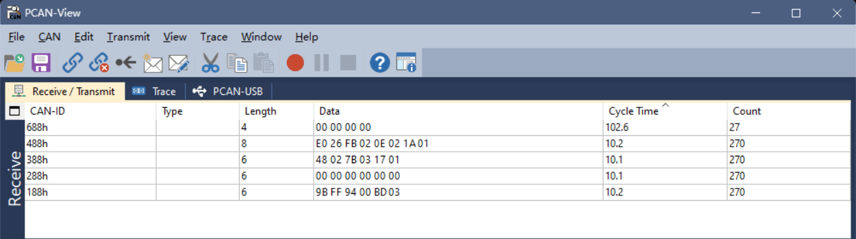
Acceleration CAN frame: ID=0x188, DATA = 4A 00 1F 00 C8 03
- ID=0x188: acceleration frame sent by the device with node ID 8
- Acceleration X = 0x004A = 74 = 74 mG
- Acceleration Y = 0x001F = 31 = 31 mG
- Acceleration Z = 0x03C8 = 968 = 968 mG
Angular velocity CAN frame: ID=0x288, DATA = 15 00 14 01 34 00
- ID=0x288: angular velocity frame sent by the device with node ID 8
- Angular velocity X = 0x0015 = 21 = 2.1 deg/s
- Angular velocity Y = 0x0114 = 276 = 27.6 deg/s
- Angular velocity Z = 0x0034 = 52 = 5.2 deg/s
Connecting to the CAN Device
Using PCAN-View with a PCAN adapter, the received CAN messages and their frame rates can be viewed in the Receive (Rx Message) window as shown below:
Configuration Commands (SDO Protocol)
The configuration commands in this section all use expedited SDO. For power-cycle retention, save the configuration to Flash after configuring.
SDO (Service Data Object) Protocol
Expedited SDO format:
Master sends SDO command to slave:
| CAN_ID | CS (1B) | Object index (2B) | Sub-index (1B) | Data (4B) |
|---|---|---|---|---|
| 0x600+ID | 0x23 (write 4 B) | LSB first | Sub-index | Data, LSB first |
Slave responds to master:
| CAN_ID | CS (1B) | Object index (2B) | Sub-index (1B) | Data (4B) |
|---|---|---|---|---|
| 0x580+ID | 0x60 (write OK ACK) | LSB first | Sub-index | Reserved |
Common Configuration Commands
Change Node ID (0x209C)
Command: ID=0x608, DATA=23,9C,20,00,[ID],00,00,00
- ID range: 1-127
- To retain across power cycles, save the configuration to Flash and reset (or power-cycle).
Save Configuration to Flash (0x2000)
Command: ID=0x608, DATA=23,00,20,00,00,00,00,00
Reset (0x2000)
Command: ID=0x608, DATA=23,00,20,00,FF,00,00,00
Restore Factory Defaults (0x2000)
Command: ID=0x608, DATA=23,00,20,00,01,00,00,00
⚠️ Warning Restoring factory defaults reverts the module to its default user configuration. After execution, the module automatically saves and resets. Some calibration-related parameters may be retained; use with caution.
Change CAN Baud Rate (0x209A)
Command: ID=0x608, DATA=23,9A,20,00,[BAUD_CODE]
To retain across power cycles, save the configuration to Flash and reset (or power-cycle).
- Change CAN baud rate to 1000 kbit/s:
ID=0x608, DATA=23,9A,20,00,00,00,00,00 - Change CAN baud rate to 500 kbit/s:
ID=0x608, DATA=23,9A,20,00,02,00,00,00 - Change CAN baud rate to 250 kbit/s:
ID=0x608, DATA=23,9A,20,00,03,00,00,00 - Change CAN baud rate to 125 kbit/s:
ID=0x608, DATA=23,9A,20,00,04,00,00,00
TPDO Configuration
The following operations write the corresponding object dictionary entries via expedited SDO. The mapping between TPDO channels and parameter indexes is:
| Channel | Frame ID | Parameter index | Description |
|---|---|---|---|
| TPDO1 | 0x180+ID | 0x1800 | Acceleration |
| TPDO2 | 0x280+ID | 0x1801 | Angular velocity |
| TPDO3 | 0x380+ID | 0x1802 | Euler angles |
| TPDO4 | 0x480+ID | 0x1803 | Quaternion |
| TPDO6 | 0x680+ID | 0x1804 | Pressure |
| TPDO7 | 0x780+ID | 0x1805 | Inclinometer |
Set / Disable / Enable Output Rate (0x1800-0x1805)
📋 Note These settings take effect immediately after writing; save the configuration separately if power-cycle retention is needed.
Common configuration examples:
ID=0x608, DATA=2B,00,18,05,00,00,00,00— disable acceleration output (1800.5=0)ID=0x608, DATA=2B,00,18,05,05,00,00,00— acceleration 200 Hz output (1800.5=5)ID=0x608, DATA=2B,00,18,05,0A,00,00,00— acceleration 100 Hz output (1800.5=10)ID=0x608, DATA=2B,00,18,05,14,00,00,00— acceleration 50 Hz output (1800.5=20)ID=0x608, DATA=2B,00,18,05,32,00,00,00— acceleration 20 Hz output (1800.5=50)ID=0x608, DATA=2B,00,18,05,64,00,00,00— acceleration 10 Hz output (1800.5=100)
Angular velocity configuration:
ID=0x608, DATA=2B,01,18,05,00,00,00,00— disable angular velocity output (1801.5=0)ID=0x608, DATA=2B,01,18,05,05,00,00,00— angular velocity 200 Hz output (1801.5=5)ID=0x608, DATA=2B,01,18,05,0A,00,00,00— angular velocity 100 Hz output (1801.5=10)ID=0x608, DATA=2B,01,18,05,14,00,00,00— angular velocity 50 Hz output (1801.5=20)ID=0x608, DATA=2B,01,18,05,32,00,00,00— angular velocity 20 Hz output (1801.5=50)ID=0x608, DATA=2B,01,18,05,64,00,00,00— angular velocity 10 Hz output (1801.5=100)
Euler angle configuration:
ID=0x608, DATA=2B,02,18,05,00,00,00,00— disable Euler angle output (1802.5=0)ID=0x608, DATA=2B,02,18,05,05,00,00,00— Euler angles 200 Hz output (1802.5=5)ID=0x608, DATA=2B,02,18,05,0A,00,00,00— Euler angles 100 Hz output (1802.5=10)ID=0x608, DATA=2B,02,18,05,14,00,00,00— Euler angles 50 Hz output (1802.5=20)ID=0x608, DATA=2B,02,18,05,32,00,00,00— Euler angles 20 Hz output (1802.5=50)ID=0x608, DATA=2B,02,18,05,64,00,00,00— Euler angles 10 Hz output (1802.5=100)
Quaternion configuration:
ID=0x608, DATA=2B,03,18,05,00,00,00,00— disable quaternion output (1803.5=0)ID=0x608, DATA=2B,03,18,05,05,00,00,00— quaternion 200 Hz output (1803.5=5)ID=0x608, DATA=2B,03,18,05,0A,00,00,00— quaternion 100 Hz output (1803.5=10)ID=0x608, DATA=2B,03,18,05,14,00,00,00— quaternion 50 Hz output (1803.5=20)ID=0x608, DATA=2B,03,18,05,32,00,00,00— quaternion 20 Hz output (1803.5=50)ID=0x608, DATA=2B,03,18,05,64,00,00,00— quaternion 10 Hz output (1803.5=100)
Pressure configuration:
ID=0x608, DATA=2B,04,18,05,00,00,00,00— disable pressure output (1804.5=0)ID=0x608, DATA=2B,04,18,05,05,00,00,00— pressure 200 Hz output (1804.5=5)ID=0x608, DATA=2B,04,18,05,0A,00,00,00— pressure 100 Hz output (1804.5=10)ID=0x608, DATA=2B,04,18,05,14,00,00,00— pressure 50 Hz output (1804.5=20)ID=0x608, DATA=2B,04,18,05,32,00,00,00— pressure 20 Hz output (1804.5=50)ID=0x608, DATA=2B,04,18,05,64,00,00,00— pressure 10 Hz output (1804.5=100)
📋 Configuration example Taking TPDO1 (acceleration) at 100 Hz (one frame every 10 ms) as an example:
0x23indicates an SDO write of 4 bytes;0x00 0x18is the index0x1800;0x05is the sub-index;0x0A 0x00is the period value10(unit: ms); the remaining bytes are zero-padded.
Set Inclinometer Zero (0x20A5)
ID=0x608, DATA=23,A5,20,00,02,00,00,00— set the current position as the output zero point (X=0, Y=0)ID=0x608, DATA=23,A5,20,00,05,00,00,00— cancel zero configuration and output real X/Y angles (equivalent to X/Y offset = 0)
Sync Protocol
The module supports configuring each TPDO into synchronous mode. When enabled, the module stops asynchronous periodic transmission and waits for the CANopen sync frame; when the sync frame arrives, it sends one corresponding TPDO frame.
Configure a TPDO into Sync Mode
To configure a TPDO into sync mode, set the corresponding TPDO communication parameter [0x180x.2] (Transmission type) to 0x01. See the standard CANopen specification for field definitions.
Taking TPDO1 (acceleration) as an example:
ID=0x608, DATA=2F,00,18,02,01,00,00,00— write[0x1800.2] = 1, set TPDO1 to sync modeID=0x608, DATA=2F,00,18,02,FF,00,00,00— write[0x1800.2] = 0xFF, set TPDO1 to async mode (factory default)
Send CANopen Sync Frame
Send a CANopen sync frame: ID=0x80, no data
When the module receives the sync frame, all TPDOs configured in sync mode send one frame of data to achieve synchronization.
Set Heartbeat
The heartbeat period is set by writing [0x1017.0], valid range 0~65535, unit: ms. 0 disables the heartbeat.
Example: ID=0x608, DATA=2B,17,10,00,64,00,00,00 — set the heartbeat period to 100 ms
Magnetic Calibration
When to Use Magnetic Calibration
9-axis mode (magnetometer-aided absolute-heading mode) is recommended when the following conditions are met:
- Perform at least one user magnetic calibration before using 9-axis mode for the first time.
- There is no obvious spatial magnetic interference in the operating environment; calibration is recommended in open outdoor areas. Indoor environments with complex magnetic conditions are unlikely to produce good calibration results.
- The relative position between the module and the mounting platform (PCB, housing, robot, etc.) remains fixed during use.
Calibration Procedure
When using the module for the first time and AHRS (9-axis) mode is required, follow the steps below:
1. Switch Mode
First, switch the module to 9-axis mode. See "Operating Mode Configuration".
2. Environment Check
Common magnetic interference sources: iron furniture, computer monitors, motors and transformers, mobile phone chargers, rebar in building structures.
Recommended calibration environments:
- Best: outdoor open area, away from buildings and vehicles (distance > 5 m)
- Acceptable: indoor area away from interference sources (distance > 30 cm)
⚠️ Important
If the module has been installed on a product PCB, or the product has a magnetic housing, or it has been installed on a robot/machine, the assembly must be treated as a whole during calibration. Calibrating the module alone and then installing it does not achieve the required effect.
3. Calibration Operation
Send the calibration command: CONFIG MCAL START (firmware version ≥ 1.7.0 required)
Perform the calibration motion:
- Within a small physical region, keep the position essentially fixed and only slowly rotate the module.
- Rotate each axis at least
360°(recommended2~3turns), at a uniform speed, around20~100 deg/s(about5~20s per turn). Avoid pauses. - Calibration usually takes
30~60s.
Recommended rotation plan: rotate 2 turns about X, then 2 turns about Y, then 2 turns about Z, or rotate randomly while making sure each axis sees sufficient angular change.
4. Query Calibration Status
Send: LOG MCAL STAT
Example response:
STAT=1
PROGRESS=8
OK
STAT field
| STAT value | State description | Suggested action |
|---|---|---|
| 0 | Idle | A new calibration can be started |
| 1 | Calibrating | Keep rotating until calibration completes |
| 2 | Verifying result | Keep stationary, wait for verification |
| 3 | Calibration complete | Success; ready for normal use |
| 4 | Calibration failed | See the troubleshooting flow; recalibrate |
PROGRESS: range 0~100, indicates the current calibration progress percentage. When PROGRESS=100 and STAT=3, calibration is successful.
5. Verify Calibration Result
- After calibration, place the module horizontally and slowly rotate one full turn (360°).
- Observe the heading output: it should change continuously from
0°to360°without jumps; acceptable error is within±5°. - If you see large jumps (>
10°) or the heading does not change with rotation, see the troubleshooting flow below.
Calibration Troubleshooting Flow
If calibration fails (STAT=4) or the verification result is abnormal, troubleshoot as follows:
Step 1: Check ambient magnetic field strength
Place the module stationary at the calibration position, read the magnetic field strength (mag_b), and compute the total magnetic field magnitude: B_total = √(Bx² + By² + Bz²).
| Magnetic field strength | Environmental assessment | Recommended action |
|---|---|---|
| 20-60 μT | Normal | Continue calibration |
| < 20 μT or > 60 μT | Abnormal | Check for nearby strong magnetic objects; move away from interference sources; change location if necessary |
Step 2: Check the rotation motion — make sure each axis is rotated at least 360° at a uniform speed of 20~100 deg/s, with no pauses.
Step 3: Check for spatial magnetic interference — measure the magnetic field strength at the same location with different orientations. If the variation is > 10 μT, there is spatial magnetic interference; change location or switch to 6-axis mode.
Common Issues and Solutions
| Failure cause | Typical symptom | Solution |
|---|---|---|
| Strong ambient magnetic interference | STAT=4 or heading jumps | Move to an outdoor open area |
| Non-standard rotation | PROGRESS grows slowly or stagnates | Ensure each axis rotates sufficiently, at uniform speed |
| Position drift during rotation | Calibration completes but accuracy is poor | Keep the position fixed during calibration, only rotate orientation |
| Module-platform relative position changes | Heading error increases after reinstallation | Treat the module and platform as a unit and recalibrate |
Important Reminders
⚠️ Warning 1: Indoor magnetic environment limitations — indoor spatial magnetic interference is severe and cannot be removed by calibration. Heading accuracy of the mag-aided (9-axis) mode strongly depends on the level of indoor magnetic distortion.
⚠️ Warning 2: Indoor usage suggestion — if the indoor magnetic environment is poor (server rooms, labs, workshops, underground parking lots, etc.), even a successful calibration may yield heading accuracy worse than 6-axis mode and large angular errors (>10°). In indoor environments, 6-axis mode is recommended.
⚠️ Warning 3: Fixed-installation requirement — if the installation environment contains magnetic interference, the interference source must maintain a fixed relative position to the module. When the module is mounted on a ferromagnetic rigid body (robot / machine / vehicle / vessel / tripod / PCB, etc.), the whole system must be rotated together during calibration. The module must not be displaced relative to the mounting platform during use; if separated, recalibrate.
⚠️ Warning 4: Motor vibration effects — vibration and magnetic interference from running robot motors can affect calibration. Calibrate with motors stopped, or calibrate while the motor is running in its working state (treating the motor field as a fixed interference source).
Calibration Frequency and Mode Selection
Calibration frequency suggestions:
- For fixed installation in a stable environment, one initial calibration is sufficient;
- For mobile applications, recalibrate after each environment change;
- Recalibrate whenever the relative position between module and platform changes;
- For long-term use (>1 year), recalibrate once per year;
- Recalibrate immediately if abnormal heading errors appear.
Mode selection suggestions:
| Application scenario | Recommended mode | Reason |
|---|---|---|
| Outdoor open environment (UAV) | 9-axis mode | Low magnetic interference; absolute heading available |
| Indoor environment (AGV, robot) | 6-axis mode | High indoor interference; 6-axis is more stable |
| Near motors / electromagnetic devices | 6-axis mode | Electromagnetic interference cannot be removed by calibration |
| Absolute heading required | 9-axis mode | Requires stable magnetic environment and proper calibration |
| Only relative heading required | 6-axis mode | 6-axis heading starts at 0 on power-up; suitable for relative measurement |
Appendix 1: Quaternion / Euler Angle / Rotation Matrix Conversion
Quaternion to Rotation Matrix
Given a quaternion
Quaternion to Euler Angles - East-North-Up (ENU)-312 rotation order (Z, then X, then Y)
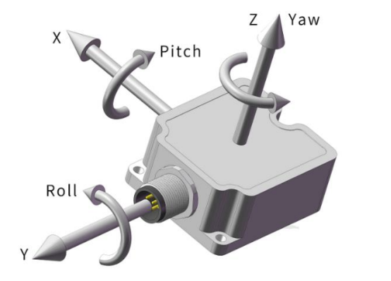
Given a quaternion
- pitch (θ): rotation about the X axis, range
- roll (φ): rotation about the Y axis, range
- yaw (ψ): rotation about the Z axis, range
Quaternion to Euler:
Euler to quaternion:
Quaternion to Euler Angles - North-East-Down (NED)-321 rotation order (Z, then Y, then X)
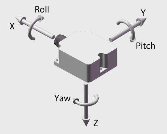
Given a quaternion
- pitch (θ): rotation about the Y axis, range
- roll (φ): rotation about the X axis, range
- yaw (ψ): rotation about the Z axis, range
Quaternion to Euler:
Euler to quaternion:
Appendix 2: Firmware Upgrade
This product supports firmware upgrade. Use the CHCenter host software and follow the steps shown below; contact technical support to obtain the firmware upgrade file (.hex).
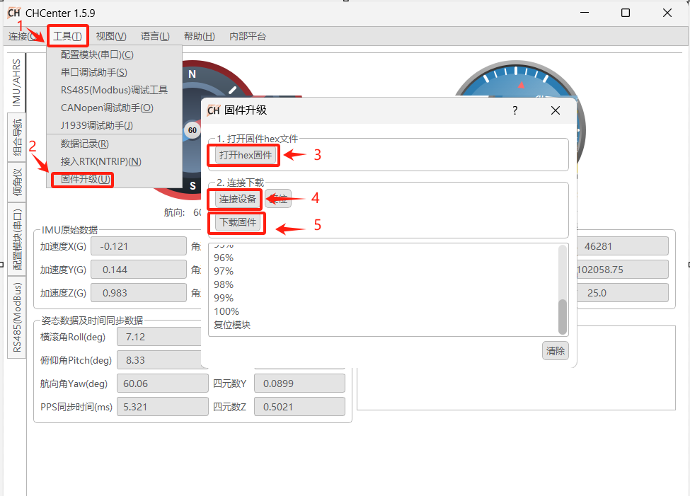
Appendix 3: More on Magnetic Interference
Magnetic interference can be divided into spatial magnetic interference and sensor-frame magnetic interference, as shown below:
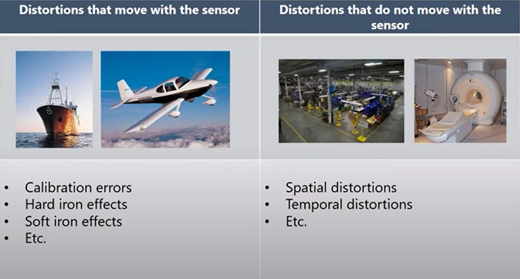
| Type of magnetic interference | Sensor-frame magnetic interference (hard-iron / soft-iron) | Spatial magnetic interference |
|---|---|---|
| Characteristics | The interference source moves with the sensor | The interference source does not move with the sensor |
| Typical sources | PCB, metal housing, UAV, etc., fixed to the module | Furniture, household appliances, cables, rebar in buildings |
| Calibration feasibility | Yes | No |
| Mitigation | Can be removed by the user magnetic calibration procedure | Cannot be removed by any calibration; severely degrades heading accuracy |
Notes on spatial magnetic interference Spatial magnetic interference is the main reason why indoor magnetometer fusion is hard to use reliably. This type of interference cannot be removed by calibration and significantly increases heading error. In indoor environments, especially near desks, chairs, and appliances, this interference is usually more pronounced.
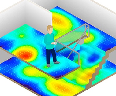
📋 Legend The figure above shows a typical distribution of indoor spatial magnetic interference: blue represents weak-interference regions, red represents strong-interference regions.
Appendix 5: Technical Support
The latest product and documentation information is available on our official website and WeChat account. WeChat: